
Bought it about 75. Built a pl 259 cable (using good coaxial cable) but the results are not great with 2 probes. On the other hand if i use a a female banana on - and a male banana on + and plug the male in female, it’s 0 everywhere. But with 2 naked male probe it’s very slightly better than before. There’s always a bout 15-20mv present to start with (non deductible).
So the probe needs to be a well inulated one and maybe having few extra components in there.
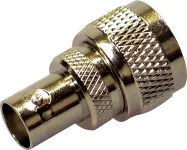
Could i use a female bnc on the other end and plug there my oscilloscope probe?
Or even go directly to an oscilloscope probe. The millivoltmeter end will always be pl 259.
So the probe needs to be a well inulated one and maybe having few extra components in there.
Could i use a female bnc on the other end and plug there my oscilloscope probe?
Or even go directly to an oscilloscope probe. The millivoltmeter end will always be pl 259.
I must say the outside of this meter looks very much like my HP 3400A. So much like it you could not tell them apart in a badly lit room. Same meter layout, same position of switches and input, same scale and position on the scale. But the insides looks a lot simpler...
First image that turned up on the net, no affiliation: https://testequipment.center/Products/HP-3400A
First image that turned up on the net, no affiliation: https://testequipment.center/Products/HP-3400A
Check the ac output of the Radiometer connected to a scope just to see
it is 50/60 Hz noise or some other pick up. Remove wireless phones etc.
it is 50/60 Hz noise or some other pick up. Remove wireless phones etc.
I’m sure it’s something like that (rf, a bit of mains hum etc), but i can’t take it away from the slightly packed bench- restricted space.
In general my mains work well for recordings etc. i’ve made. A 1:1 custom line and ii have it on that 1:1 isolated supply line. Not a top one but still good enough.
I will buy the adapter and see how it goes. In case things are the same ( i think with the oscilliscope probe things will be much better - since when the probes are isolated things are way better) i will replace the old filter caps and if i see no improvement i will just work as i can with it. What else could i do…
Hi,
while those instruments share a optical similarity they are quite different electrically.
The instrument talked about here is averaging the signal voltage ... giving rms value only for sine signals.
After signal conditioning it rectifies and smoothes the signal (CR105/CR106/C118).
A cheap and easy way, found in many of the cheaper instruments.
The also mentioned HP3400 uses a pair of thermal sensors within a control loop featuring a chopper amplifier.
This way it can measure the true rms value of any signal shape.
More precise and alot more effort required ... since their higer prices.
Similar and even more capable is a sensor like the -long since obsolete- LT1088 manufactured by Linear technology.
This chip also features a pair of sensors (Diodes instead of Thermocouples in this case), within a control loop with a linear amplifier.
But that would probabely end in a DIY solution .... I don´t know of a commercial RMS-Voltmeter utilizing this chip.
jauu
Calvin
The essential benefit of a millivoltmeter is not to find valid RMS data,
but to detect and combat noise.
However it is good enough to perform accurate gain and attenuation
investigations also, because sinusoidal waveforms will be used.
In other words a true RMS instrument is not required in daily life.
but to detect and combat noise.
However it is good enough to perform accurate gain and attenuation
investigations also, because sinusoidal waveforms will be used.
In other words a true RMS instrument is not required in daily life.
Sorted. The pl to bnc adapter is gold and oscilloscope probe apparently is a must for this simple oscilloscope (checked the insides of the hp and it’s way more complicated).
When shorted zero on every scale. Measurements as accurate as can be with this tool.
Thanks everyone for the input and great ideas.
I will soon start a new thread because i also need to calibrate my old analog signal generator.
When shorted zero on every scale. Measurements as accurate as can be with this tool.
Thanks everyone for the input and great ideas.
I will soon start a new thread because i also need to calibrate my old analog signal generator.
Calibrated the signal generator. With banana plugs on it and pl on the meter the lowest i can get is 1.5mv rms from 4.5mv p-p. Below that i have to move to the 1mv scale on the signal generator and it just doesn’t work properly. But i don’t really care that much since this nr is the lowest i’ve ever measured on any of my test equipment.
Hi,
"The essential benefit of a millivoltmeter is not to find valid RMS data,
but to detect and combat noise"
Could You explain why that should be so?
The RV36 is specced with 50µV of noise and the HP3400 with <1mV.
Certainly not so well suited to evaluate noise wo. a dedicated lownoise amplifier ahead.
I also wonder why such a renowned company like HP would have explicitely gone the hard way building a true-RMS device and named it "RMS Voltmeter" if they hadn´t seen a requirement for daily life useage?
Maybe because a clean sinusoid is rather the exemption than the rule among daily life signals?
jauu
Calvin
I am sure you know all this.
A good millivoltmeter is "a dedicated low noise amplifier". For this use the
position of the pointer is not relevant, the ac output of the device is scope
connected for a clear picture of what is going on in applications where scope
sensitivity is not sufficient and also to limit bandwidth to a relevant range.
In my view it is useless to build your own LNA, because these instruments
are available for cheap money.
I can not comment on HPs design decisions, but the number of "ordinary"
HP ac voltmeters probably exceeds that of true RMS types. Hewlett Packard
products are not always the best for daily life DIY use.
"Daily life": how often do you use an instrument like this for comparative
gain investigations and how frequently to look at noise etc, do you use any ?
The RMS values of triangular and square waveforms are not interesting to
measure in daily life, because you can see their RMS on the scope screen.
Not sure why anybody in DIY would want to know RMS of other signals.
Daily life in DIY is sine, square, sometimes triangle and - noise.
A good idea would be to gather valid RMS results for noise at low levels
and ths is where a true RMS voltmeter does not excel. You bring up the
difference of about 26 dB for both mentioned devices.
The Radiometer RV36 is old, but "good enough" here. Better alternatives
and characteristics to look for may be discussed somewhere else.
Last edited:
Update for future reference:
After calibrating the generator as good as posdible, i ordered a banana (2 male) to bnc (female) adapter.
When it arrived i tested everything again. I added a bnc male to rca female on that.
Then i connected that adapter combo on the generator, used a 1k sine, and used an excellent rca cable.
That went to an rca (female) to pl 259 (male) adapter on the millivoltmeter. All very tight.
Result? The millivolt meter measured minimum values around an impressive (for me) 0,15 mv.
Now i feel like i can work properly. A very nice reasonablu]y priced millivoltmeter.
In the future i will order another banana - bnc adapter just to measure with the multimeter just for testing purposes.
- Home
- Design & Build
- Equipment & Tools
- Old analog milli voltmeter, doesn’t read low mv values