
😀😀Yeap!!!😀😀
and the 390's at 450 four of them...
along with nichicons 1000uf at 100 about 30 of them
 I have got a board to layout...
Thanks
and the 390's at 450 four of them...
along with nichicons 1000uf at 100 about 30 of them
I have got a board to layout...Thanks
Last edited:
hi luka and others,
iam about to complete the board.just transformer remaining.
here are the calculations for etd 49 50-0-50 5amp each.
vin low=254
vin high=382
highest average current=po/vin low
500/254=1.96amp
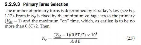
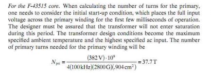
no of primary turns
np=vin min x10^8/4xfxbxac
=127x10^8/4x50000x2100x2.11
=14.33 turns or 15 turns
calculating skin depth
sd=6.62/sqrtF
=6.62/sqrt50
=0.0296cm
wire dia =2xsd=2x0.0296
=0.0592cm
bare wire area
3.14xwir dia/4
=3.14x(0.0592)^2/4
=0.00275 square cm
ill be using swg wires
so 23swg=0.610mm
bare wire area using 23swg=0.00292 square cm
primary bare wire area
awp=Iin pri x sqrt dmax/j
assuming 500cirmills/amp and duty cycle of 0.95
=1.96 x sqrt0.95/500
=0.00382cm2
no of strands required for primary
=awp/swg23=0.00382/0.00292
=1.30 or 2 wires of 23swg for primary
secondary turns
nsec=1.1(vout+vd) x npri/vin min x dmax
=1.1(50+1) x 15/127 x 0.97
=6.97 or 7 turns
no of strands for secondary=3.32 or 4 strands
are these calculations ok
can i use mur 160 instead of sb160.will post pics as soon as transformer gets completed.i will be using cosmo ferrites cf139 material.
http://www.cosmoferrites.com/material_info.html
many questions to come.
thanks in advance
ravs
be a vegeterian.......
iam about to complete the board.just transformer remaining.
here are the calculations for etd 49 50-0-50 5amp each.
vin low=254
vin high=382
highest average current=po/vin low
500/254=1.96amp
no of primary turns
np=vin min x10^8/4xfxbxac
=127x10^8/4x50000x2100x2.11
=14.33 turns or 15 turns
calculating skin depth
sd=6.62/sqrtF
=6.62/sqrt50
=0.0296cm
wire dia =2xsd=2x0.0296
=0.0592cm
bare wire area
3.14xwir dia/4
=3.14x(0.0592)^2/4
=0.00275 square cm
ill be using swg wires
so 23swg=0.610mm
bare wire area using 23swg=0.00292 square cm
primary bare wire area
awp=Iin pri x sqrt dmax/j
assuming 500cirmills/amp and duty cycle of 0.95
=1.96 x sqrt0.95/500
=0.00382cm2
no of strands required for primary
=awp/swg23=0.00382/0.00292
=1.30 or 2 wires of 23swg for primary
secondary turns
nsec=1.1(vout+vd) x npri/vin min x dmax
=1.1(50+1) x 15/127 x 0.97
=6.97 or 7 turns
no of strands for secondary=3.32 or 4 strands
are these calculations ok
can i use mur 160 instead of sb160.will post pics as soon as transformer gets completed.i will be using cosmo ferrites cf139 material.
http://www.cosmoferrites.com/material_info.html
many questions to come.
thanks in advance
ravs
be a vegeterian.......
Last edited:
Off Line Switcher
What Is Your Output Power Level??
Possibly a 2-Switch Forward Converter will work for you - it is a MUCH More Robust Topology with FAR fewer Complications and you only have 2 MOSFETS To Drive.
With a 2-Switch Forward your MOSFET Voltage Stress will be the same as the Full Bridge
Steve
What Is Your Output Power Level??
Possibly a 2-Switch Forward Converter will work for you - it is a MUCH More Robust Topology with FAR fewer Complications and you only have 2 MOSFETS To Drive.
With a 2-Switch Forward your MOSFET Voltage Stress will be the same as the Full Bridge
Steve
hey ravs,
I will check later today... primary count seems to be really low, but can't say its not ok
I will check later today... primary count seems to be really low, but can't say its not ok
hey ravs,
I will check later today... primary count seems to be really low, but can't say its not ok
hi luka,
i used vin low 180 vac rectified 254vdc and half of it 127vdc for half bridge
which one you go with
thanks in advance
ravs
be a vegeterian....
Attachments


hi luka,
waiting for your response, one more thing how did you come to the point using 2 wires
of 1mm in primary is it considering low line input voltage current of 1.96 amp.then what about the peak input current of 5.51 amp.
thanks
ravs
be a vegeterian....
waiting for your response, one more thing how did you come to the point using 2 wires
of 1mm in primary is it considering low line input voltage current of 1.96 amp.then what about the peak input current of 5.51 amp.
thanks
ravs
be a vegeterian....
oh man, so sorry, I work crazy hours this days....
so, I get 15 turns for primary @ low input also, that is ok
with 50kHz you can still use 1mm wire, no problem, its what I got, only 1mm wire
One thing you need to understand here is this: you can use more then 4A for every 1mm2 of wire you have, since this peak is not constant, also you probably will never have that low input voltage... if you know you will, I would really think about PFC at this point
So by using 2 or even 3 primary wires, since you only have 15 turns... here I would go and use 16 or 18...
say you use 18, then I would use 8 for secondary.
You can use any fast diode, mur, sb,... that is for gate drive? even 1n4148 is ok there.
So about a wire...if you like it, like me, test it, use only 1 primary wire, and see what you get, then use 2... you will then see how smps will behave...if you have scope to check... but in any case you MUST use copper, and not leave trafo empty... did do that myself a lot of times and none of them were as good and use bit more wire
Hello SMPS expert,
I have lot of IR2116 came from electronic ballast and of caurse it is specialized application for electronic ballast, my question is can I used this IR2116 instead of ir2110 for FET driver? Thanks and happy new year to all.
rlg,
I have lot of IR2116 came from electronic ballast and of caurse it is specialized application for electronic ballast, my question is can I used this IR2116 instead of ir2110 for FET driver? Thanks and happy new year to all.
rlg,
hi luka,
belated happy new year to you and all.
yesterday i started powering the control section of smps.without any powe device and ac.
on giving 12 volt to sg3525 and ir2110 i get the following voltages since i have no scope.iam using 47u instead or 33uf for start up cap.
on pin 14 , 11 of sg3525 iam getting 5.39 and 5.40 volts and when i insert ir2110 i get
5.40 and 10 volts on pin no 7 and 1 or ir2110 is this normal.sg3525 voltages remain the same.
thanks in advance
ravs
be a vegeterian.....
.
Last edited:
I can't find this part... my guess is, that no, you can not change it, since that is dedicated ballast driver if it isHello SMPS expert,
I have lot of IR2116 came from electronic ballast and of caurse it is specialized application for electronic ballast, my question is can I used this IR2116 instead of ir2110 for FET driver? Thanks and happy new year to all.
rlg,
Happy new year too you to!hi luka,
belated happy new year to you and all.
yesterday i started powering the control section of smps.without any powe device and ac.
on giving 12 volt to sg3525 and ir2110 i get the following voltages since i have no scope.iam using 47u instead or 33uf for start up cap.
on pin 14 , 11 of sg3525 iam getting 5.39 and 5.40 volts and when i insert ir2110 i get
5.40 and 10 volts on pin no 7 and 1 or ir2110 is this normal.sg3525 voltages remain the same.
Now,
you can't meter pins 14 and 11 with normal meter, you could measure freq., if meter has that option, same goes for pins 1 and 7 of IR... you can't do nothing without scope or scope meter... go and find some used, old one, even if it is <<<20MHz
My guess would be that it works ok, but no way to tell if you can't see waveforms
hi luka,
i blown my 2110 and irfs.with bulb in series.everything seems to be ok.bulb blinks for a
less than a second.first i soldered the transformer and mosfets plugged through the bulb.
again bulb lights for a second.but i couldnt measure the ac voltages on the transformer
output.now i soldered the diodes and filters .the readig goes out of 600 volts dc range.
of meter . then i connected a load of 200 watt bulb on output.reading comes to be 70 volts.both bulbs were lighting continuosly.i thought because it is loaded thats why the
is lighting continuosly.i measured voltages on pin 1 and 7 f ir2110 in 20 volt dc range they came to be 5.40 and other goes out of range .i removed the series bulb and plugged directly the fuse blown it was only 1 ampere i replaced it with 3 amp now nothing happens for a second then with a little hiss new year ffireworks starts .
i have seen in many dc-ac invertors both side mosfet get the same level drive voltage.
luka could you please measure these voltages for me in your smps.since i have no cro.
ill try again.
thanks in advance
ravs
be a vegeterian....
- Home
- Amplifiers
- Power Supplies
- Offline full-bridge SMPS… need help