Re: LUKA SMPS
Something you will find usefull... for others too

norazmi said:
Regards.
Azmi
Something you will find usefull... for others too
O yea, I forgot to answer... you shouldn't have air gap, but I also think you maybe won't be able to get rid of it, probably will make other legs worse... for now leave as it isLuigiDJ said:Another question: the etd59 core have a gap in the center leg less than 1 mm) , should i leave like this or should i try to level the legs so there is no gap? (i'll try to do this with some fine sand paper and water over a glass panel so everything is flat).
Thanks 😀
LUKA SMPS
Hi Luka,
Thank You, i`ve got all the file. Firstly i would like to ask, refer to the top silk on your board, there are few component that doesnt have component number with blue circle and question mark. Its adjustable value for that component?
For you information, in my country we are using 220-240 vac 15 amp. i would like to have output 30-0-30 vac with at least 5 amp each. Do you have any suggestion for it?
Also another question is, how do i parallel the mosfet IRFP450? Can i use irf740 instead of IRFP450? Maybe parallel of irf740 will be great.
Regards.
Suggestion...
Hi there,
Few month a go i`ve mods PC supply, Below i`ve attach the original schematic. From here as we can see for Q1 and Q2 2sc4242 or mje13007@mje13009 and other similar type of power transistor.
how do i parallel the transistor for Q1 and Q2? Its possible to do that?
btw i`m in progress of making LUKA SMPS board maybe for few days when i can get complete component to finish it and test it. i`ll post here too.
Regards.
An externally hosted image should be here but it was not working when we last tested it.
Re: LUKA SMPS
No, as you can se, left blur circle is fast diode [mur120], and right one is where secondary [aux] comes tonorazmi said:Hi Luka,
Thank You, i`ve got all the file. Firstly i would like to ask, refer to the top silk on your board, there are few component that doesnt have component number with blue circle and question mark. Its adjustable value for that component?
You probably mean Dc, so +/-30v and 5A? yea pretty easy, even less then my voltage, in fact you can get ANY voltage you need, you just need a bit diffrent trafo ratio, input is the same as here, so no problem thereFor you information, in my country we are using 220-240 vac 15 amp. i would like to have output 30-0-30 vac with at least 5 amp each. Do you have any suggestion for it?
Can't you just use one set of fets? [IR will be thankfull] And 450's are like oooooverkill, you can use other 400v+ few amps fets too, I put those for big overkill, so nothing I do will kill themAlso another question is, how do i parallel the mosfet IRFP450? Can i use irf740 instead of IRFP450? Maybe parallel of irf740 will be great.
Re: Suggestion...
But yes you can heve more then one Q1s and Q2s

You can not parallel Q1, Q2, this is also half bridge, so you will always have this two in series like you see, you could parallel Q1 and Q2, but I don't see why you would need to do that here, you don't need that much power, also note that this are BJTs, I use fetsnorazmi said:Hi there,
Few month a go i`ve mods PC supply, Below i`ve attach the original schematic. From here as we can see for Q1 and Q2 2sc4242 or mje13007@mje13009 and other similar type of power transistor.
how do i parallel the transistor for Q1 and Q2? Its possible to do that?
Regards.
But yes you can heve more then one Q1s and Q2s
Cool, post pics, I will put them on my site for everybody to seebtw i`m in progress of making LUKA SMPS board maybe for few days when i can get complete component to finish it and test it. i`ll post here too.
LUKA SMPS
Hi there,
Thanks alot Luka for usefull answer and explain almost everything in my question. Yes you`re right when using IRFP450-460`s its overkill for the power, 2 pair is enough to have power up to 1KW. At the output stage can i use ultra fast diode like MUR420@MUR460? Can i use MJE13005 instead of tip50? I`m plan to use irf740 pair so what estimate output power in watts i can get?
Then, refer on your schematic, R15&16 is 680 ohm but there is some notes there to use 2.2Kohm instead 680? so i should change it to 2.2Kohm for R15&16? I`ve on hand now 2.2K 3w so if its yes than i`ll not order 680 ohm otherwise need to order it again. I`m still waiting for ir2110 which i dont have it yet.
i`m using manual etch system only by hand 😀 . For now i`ve order some few part and waiting for them.
i`ll post the picture of the board before testing it to make sure if i`ve any error on the board.
This is my first time build offline smps using mosfet. Thanks to Luka for the sch and board and i`m making it for myself. Electronic is my hobby at home.
Regards.
Azmi
Re: LUKA SMPS
norazmi said:Hi there,
yes you can, but I would use more then one per diode [my that is, my has bigger current rating, more safe to use]At the output stage can i use ultra fast diode like MUR420@MUR460?
you can use any that is more then 350v rating [350v just to be sure]Can i use MJE13005 instead of tip50?
well it is 10A fet, not bad at all, it does have a some Rds resistance, but should not be a problem. I think you will get 1kw easy if you would need that muchI`m plan to use irf740 pair so what estimate output power in watts i can get?
yes I used 680, but then seen when testing that it could be even more, to create more voltage drop on them. But since this circuit works <<1s easy time you turn on smps, it doesn't matter that much, so you can change it to 2.2Kohm or anything from 680 to 2.2k if you already have someThen, refer on your schematic, R15&16 is 680 ohm but there is some notes there to use 2.2Kohm instead 680?
yes 2.2k is ok, you will later see if you will need to change them or not. But you need Aux to work, or this part of circuit will be making voltage for IR and SG, and that means huge voltage from from main caps down to say 15v or how you will set yoursve on hand now 2.2K 3w so if its yes than i`ll not order 680 ohm otherwise need to order it again. I`m still waiting for ir2110 which i dont have it yet.
Hope it works first time for you tooi`m using manual etch system only by hand 😀 . For now i`ve order some few part and waiting for them.
i`ll post the picture of the board before testing it to make sure if i`ve any error on the board.
This is my first time build offline smps using mosfet. Thanks to Luka for the sch and board and i`m making it for myself. Electronic is my hobby at home.
Regards.
Azmi
Some test
Hello everybody.
Just wanted to show how my SMPS is working. Now it's output voltage is +/- 71 and is running at 50 KHz. I changed Rt to 27K ohms, Ct is 1 nF. ETD59 was rewound to 20 turns primary, 4 strands of 22AWG, secondary is 9+9 turns, 6 strands of 22 AWG. First I wind half the primary, then half secondary, then last half primary, and then the other secondary.
The IC's voltage is obtained from an auxiliary transformer, later I'll add the startup circuit.
Output caps is now 1 x 470uF/200V per rail, I'll get 2 x 1000uF/100V per rail, or better 3 x 470uF/100V per rail, what do you think? (it's for running audio amp at 200W/channel)
I'll do more test with some 100W bulbs and post pics of current and voltage.
The gap in the core, i could eliminate it with the sand paper trick, the surfaces are smooth and they make contact without any gap at all (i didn't took photos of the process 🙁 ) Is it advisable to glue the 2 parts of the core?
Can a bleeder resistor be added to the outputs? Can it be used as a minimum load?
Again, thanks to everybody that contributed to this post, and luka for this design.
Post pics of yours, i had fun making this, hope you too 😀
Attachments
nice work!
3x 470u would be probably best,or 3x 1000u3 x 470uF/100V per rail, what do you think?
you can glue 2 parts of core togetherIs it advisable to glue the 2 parts of the core?
Yes!Can a bleeder resistor be added to the outputs?
You can, but you don't need minimum load or then again amp itself is a loadCan it be used as a minimum load?
I would keep the minimal-load resistors for testing as SMPSs don't like to run in no-load conditions, and in case either Amp's power leads should accidentally be disconnected from the SMPS's outputs. Just a thought.
Other than that very small item, I like it. Can you post a schematic?
Cheers,
Steve
Other than that very small item, I like it. Can you post a schematic?
Cheers,
Steve
Forgot that it was your design. Doh!  Trying to do a lowly MOSFET half-bridge. Will post pc board patterns in a new thread.
Trying to do a lowly MOSFET half-bridge. Will post pc board patterns in a new thread.Hey Luka-
What did you do your board with? I am doing mine with ExpressPCB. If you have a file of it, can you email it to me? Thanks,
Steve
What did you do your board with? I am doing mine with ExpressPCB. If you have a file of it, can you email it to me? Thanks,
Steve
luka said:hey DJ,
Post waveforms too, when you'll find time for this
Hello luka, sorry, I can't post waveforms, I don't have an oscilloscope
 , but I'm thinking on making a PIC based scope, just for the fun of having a scope 😀
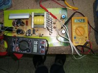
 More testing: I put 3 x 80 ohms in parallel on each rail (26.666ohms) and on input I got 3.58 Amps (120 Vac), so it's 429 watts, right? On output I calculate 70^2 / 26.666 = 183 watts each rail, so it's 367 watts in total. Efficiency is (367/429) x 100 = 85%

Mosfets were just a little bit hot, same the transformer, diodes were normal temperature, but loads were very hot, so I didn't test it for a long time, maybe 5 minutes or so...
Next thing will be to connect it to the amp, will post pics when I do.
Attachments

N-Channel said:Forgot that it was your design. Doh!
Hello N-Channel, yes, all credit for the design goes to luka. I'm just a follower, but I did learn a lot of new things with this thread. Could you post a link to your thread so we can visit?
Thanks.
- Home
- Amplifiers
- Power Supplies
- Offline full-bridge SMPS… need help