Hello everybody
I read all the thread, and I'd like to build this SMPS. Input will be 120 Vac, and output will be +/-70Vdc @ 700 watts for 2 amp modules.
I'm going to use an ETD59 core taken out from a Marconi power supply, I also took out 4 diodes (BYV52-200), 2 MOSFET (W20NB50), some capacitors and some toroid inductors.
With all this, I have some questions: 1- Is it posible to build it with the 120 Vac input without major mods? (of course, using the voltage doubler connection posted some pages behind)
2- My recycled components are OK to build this? (I'll mod the pcb to fit the core and the diodes)
3- In the schematic , there is a resistor (2.2k)connected to the SD pins of IR2110 and SG3525, I can't find its location on the PCB (is it because is a SMD resistor?). Also, they are connected in the PCB to pin 14 of IR2110, and the schematic says that pin 14 is NC. Should pin 14 of IR2110 be left NC?
4- Could the SD pins be connected directly to GND , as I saw on the "50KHz SMPS - 900 Watt out", by Veysel Arslan, that was posted also in the thread?
5- My ETD59 core has a gap in the center leg. Is this normal for these cores? Will this affect something on the design?
(first post in the thread, and already making too much questions 😀 )
I'll calculate the turns for my core and voltage and post them.
Thanks in advance...
🙂
1) Half bridge = no ETD core gap. Can't reuse old cores even tho ETD59 bobbin s/b correct size for 700 watts.
2) D8-D11 in parallel is not sharing current equally.
3) your regulation point s/b connected to main secondary outputs (not shown yet?)
4) No current limit in primary
5) 120V is half wave so use 2 rectifiers only (D1 not bridge) still center floats
6)
2) D8-D11 in parallel is not sharing current equally.
3) your regulation point s/b connected to main secondary outputs (not shown yet?)
4) No current limit in primary
5) 120V is half wave so use 2 rectifiers only (D1 not bridge) still center floats
6)
correction
5) D1 OK, 110V operation disconect AC Neutral from D1 and connect to center of storage capacitors.
5) D1 OK, 110V operation disconect AC Neutral from D1 and connect to center of storage capacitors.
Contact
Olá Xará!!
André(paladinox). Se possível gostaria de entrar em contato com vc, tenho alguns projetos de fontes chaveadas bem parecidos com o q vc postou acima. Sou novo no fórum e ainda não posso ver seu e-mail!
André Sobral
robota_mecatronica@yahoo.com.br
Olá Xará!!
André(paladinox). Se possível gostaria de entrar em contato com vc, tenho alguns projetos de fontes chaveadas bem parecidos com o q vc postou acima. Sou novo no fórum e ainda não posso ver seu e-mail!
André Sobral
robota_mecatronica@yahoo.com.br
Hi, it would be informative if you could show pictures of gate drive signal, primary coil voltage and secondary coil voltages.
The transformer might have been wound in incorrect way. You should have tight layers of wires filling the whole width of the bobbin. Having loose wirings and random wire placement within layers result in high leakage inductance which reduces the coupling between primary and secondary coils. You'll see this if you check the coil voltages (or secondary diode voltages). What is the DC voltage you'll have at the secondary side?
Also make sure you have the secondary coils are wound in right "direction", so that the dot ends are correct.
If you can, bypass the control circuitry and drive the MOSFETs in open-loop. You can make the error voltage with a potentiometer for example. I have done this myself, driving a full-bridge converter with constant duty cycle (resistive load). This way the possible failures in the feedback circuitry won't blow your precisious components.
Good luck!
I think I have layout problems with IR2110.
Now, I'm developing another PCB, with some new advices.
I really have a bad relation between primary and sec voltage. That does not match with turn ratio, is smaller. Is this a coupling problem?
I bought some T6325 toroid. Really big! Now, will recalc and rewind.
Thanks
Now, I'm developing another PCB, with some new advices.
I really have a bad relation between primary and sec voltage. That does not match with turn ratio, is smaller. Is this a coupling problem?
I bought some T6325 toroid. Really big! Now, will recalc and rewind.
Thanks
primary and sec voltage ratio under load? I could be and some really bad waveform on top of that
But that is not the problem, not from IR..
But that is not the problem, not from IR..
About IR layout, is about burning FETS. Not waveforms or turn ratio.
The relation between prim and sec is wrong with NO LOAD.
The relation between prim and sec is wrong with NO LOAD.
post some pic, let me see you PCB. I didn't burn any of my IRs, bad layout and all
about you trafo, before I ask anything else, what volgates does it put out and what should it be. Also what is your ratio?
about you trafo, before I ask anything else, what volgates does it put out and what should it be. Also what is your ratio?
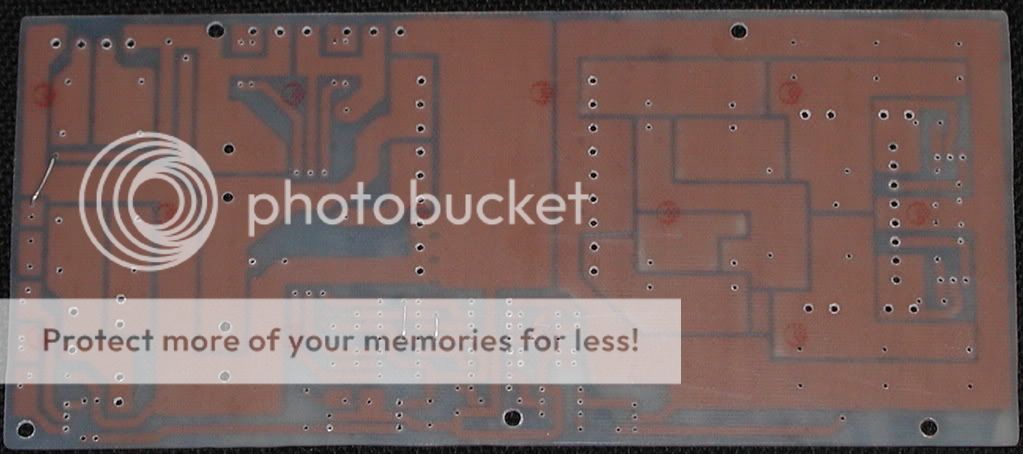
PCB:
[img=http://img7.imageshack.us/img7/1069/layouthwx.th.jpg]
or
http://img7.imageshack.us/img7/1069/layouthwx.jpg
Trafo is about 24 turns primary and 2 sec.
I have less than 11V in rectified output.
[img=http://img7.imageshack.us/img7/1069/layouthwx.th.jpg]
or
http://img7.imageshack.us/img7/1069/layouthwx.jpg
Trafo is about 24 turns primary and 2 sec.
I have less than 11V in rectified output.
I can tell you already you coupeling is bad, you will need to fix this, but as I see it, you are trying to have voltage lower then 10v, why so?
and you are right, why is IR sooooo far away from fets, you have tons of open space near them
and you are right, why is IR sooooo far away from fets, you have tons of open space near them
I'm trying to have 14V DC output for battery charge or power suply for automotive purpose.
Like I told, I just bought some toroid cores, (T6325) so, will rewind and bye bye transformers problems.
The new PCB layout is here:
http://img15.imageshack.us/img15/9238/layout2c.jpg
Any advice on layout?
Can you give-me some tips about widing so low number of turns?
Never will get all the core wired. Really thanks for helping.
PCB Layout
If you would like a robust design you should consider referring to appnotes on proper board layout for digital and analog signals a good source is Marty Brown"s "Power Supply CookBook" refer to pages begining with page #96; TI also has a appnote in PDF format on thier website also do a google search. You should leave as much copper on the board as possible, make high current traces wide (note you can also google for info on current handling capacity of pcb traces) for starter's look here http://www.smps.us/layout.html To get an idea get an old pc supply "450 watts" and look at the layout you should notice how the input power is separated from the output and the grounding is also separate. keep signal leads as short as possible, also bypass components for controller should be close to IC pins as well as timing components.
A question arises PC supply's kick out 500 watts with a very small transformer with 12 volt supply over 4amps, 5volts@40amps and there is info on the web to mod these to provide a single output of 13 volts upto 20 amps.
chas1
Thanks chas. I tried to find a specific appnote about pcb design, no success. Maybe you can give me some links, if possible.
http://www.smps.us/layout.html has some good information, most of them already used in the second layout I posted.
About the isolation between primary and secondary, is this necessary?
I have same gnd net, ICs, FETS... Not output.
Usualy I use iron solder to increase current handling in all high current traces. Since this is in learning mode yet, I can spend some time.
I'll go 100A 14V. Thanks for reply.
use my pcb as some guide, you can make it a lot smaller then that!
Ir and everything can be and should be just next to fets, input caps not far from trafo,...
Ir and everything can be and should be just next to fets, input caps not far from trafo,...
Isolation
Is this a dc to dc conveter?, and for that current you might consider copper foil in the secondary and also buss bar type output connections. The pcb layout you have will not handle that current .
chas1
Is this a dc to dc conveter?, and for that current you might consider copper foil in the secondary and also buss bar type output connections. The pcb layout you have will not handle that current .
chas1
he is right, but I still think this is AC one, not DC. For that current I would look into having more then one trafo..
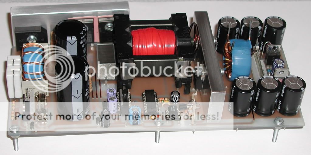
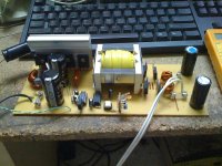
OK, I made it! This is my SMPS, following luka's design. I'm testing it with 100 Vac and I'm getting 114Vdc. Tomorrow will begin testing with 127 Vac (line voltage). I used the voltage doubler "trick" because in my country is 127 V. I had to alter the pcb, because I'm using ETD59 core, and it didn't fit on the original pcb.
I want to get +/-70Vdc @ 8 Amps (or a little more) to run 2 amp modules.
Primary is 24 turns of 3 wires 19AWG. Secondary is 12+10 turns (ran out of wire to complete the other 2 ) of 5 wires 19AWG. I'll test it like this for now...
What could be a good load to test a SMPS like this? some bulbs in parallel, or a dummy resistor?
Another question: the etd59 core have a gap in the center leg less than 1 mm) , should i leave like this or should i try to level the legs so there is no gap? (i'll try to do this with some fine sand paper and water over a glass panel so everything is flat).
Thanks 😀
I want to get +/-70Vdc @ 8 Amps (or a little more) to run 2 amp modules.
Primary is 24 turns of 3 wires 19AWG. Secondary is 12+10 turns (ran out of wire to complete the other 2
) of 5 wires 19AWG. I'll test it like this for now... What could be a good load to test a SMPS like this? some bulbs in parallel, or a dummy resistor?
Another question: the etd59 core have a gap in the center leg less than 1 mm) , should i leave like this or should i try to level the legs so there is no gap? (i'll try to do this with some fine sand paper and water over a glass panel so everything is flat).
Thanks 😀
Attachments
LUKA SMPS
Hi there,
I`m sorry, i already follow this thread 3-5 days and try to understanding, i really like LUKA design, btw because of sometimes schematic updates and also pcb, i would like to request from luka if you can sent me an email your final schematic and pcb layout. I want to build it since i`ve follow this thread and got some experience with many expert discussion.
xwebmaster@gmail.com
Regards.
Azmi
Yea light bulbs, that would be good starting point, but also you have to know they start cold, so more current is needed [probably not a problem]. But I use several heating elements, like ones in old heater for rooms, or electric ovens,... they have about 65R [220-240v versions] and can handle a lot of power >>500w each. So I wire them as I need the resistance to be...LuigiDJ said:What could be a good load to test a SMPS like this? some bulbs in parallel, or a dummy resistor?
Another question: the etd59 core have a gap in the center leg less than 1 mm) , should i leave like this or should i try to level the legs so there is no gap? (i'll try to do this with some fine sand paper and water over a glass panel so everything is flat).
Thanks 😀
that is all for high power tests, small test you can use pretty much anything that will do the job
post picture when can
- Home
- Amplifiers
- Power Supplies
- Offline full-bridge SMPS… need help