Thanks, Luka.
Have you tried what happens to both output voltages if you load them different, when the supply is working regulated?
For example, if you load with 20mA in one side and 150mA in the other side, does the voltage drop in the most loaded rail?
The coupled inductors are supposed to minimize this effect, but have you verified this point?
Hi Pierre
You don't want to load them asymmetricly, well not sure for such currents, but if one is more loaded then other and smps is regulated then voltage on heavier loaded line will drop, other will rise, both together will still have voltage that smps is regulated to, but that is in case that you take feedback from + and - rail. Don't know how would be if only from + and GND, probably a bit diffrence in voltage, but not that much for such currents. This smps/my is for audio use so both will be loaded, and I won't have this problem.
I have only done large power tests, load connected from + to -, but even if you don't have coupled inductor I thing you shouldn't have any problems, not any big ones anyway
Lets try to make similar SMPS using ferrite transformer for driving mosfets and dual bipolar for driving ferrite
😀
If mosfet burns here the circuit would be destroyed ?! cause burned mosfet can have full voltage on the gate
luka can you post scope of that driver circuit attached to mosfet : if you already made some tests?
😀
If mosfet burns here the circuit would be destroyed ?! cause burned mosfet can have full voltage on the gate
luka can you post scope of that driver circuit attached to mosfet : if you already made some tests?
Hi
If I used gate trafo to drive mostets? No I don't plan doing that soon. I don't see how will circuit be destroyed when mosfet fails if you use trafo or IR like I do
Which circuit do you mean??
If I used gate trafo to drive mostets? No I don't plan doing that soon. I don't see how will circuit be destroyed when mosfet fails if you use trafo or IR like I do
Which circuit do you mean??
luka said:Hi
If I used gate trafo to drive mostets? No I don't plan doing that soon. I don't see how will circuit be destroyed when mosfet fails if you use trafo or IR like I do
Which circuit do you mean??
But burned mosfet can have full voltage on the gate like I said
that for sure can burn IR driver dont you agree?!
But it does not seem as problem IR is a good driver... after all if circuit is good there should be no problems
But I would prefer ferrite trensformer for driving cause it has "galvanic separation" and more safety
Hi
IR can withstand voltages up to 500v for my version or 600v for better one. Don't know thy do you thing fet will fail, use big enough and you wont have any problem ot all, but trafos have some better points, like isolated gate drive
IR can withstand voltages up to 500v for my version or 600v for better one. Don't know thy do you thing fet will fail, use big enough and you wont have any problem ot all, but trafos have some better points, like isolated gate drive
luka said:Hi
IR can withstand voltages up to 500v for my version or 600v for better one. Don't know thy do you thing fet will fail, use big enough and you wont have any problem ot all, but trafos have some better points, like isolated gate drive
But MAIN trafo without load can have high HV peaks
; I cant see you have zenner protection on the mosfet?
Or you think series capacitor will prevent HV peaks on the mosfets DS, I dont know
Are you making SMPS for an amplifier?
Hi
There are no spikes at all, you don't even need zeners to protect gates, I don't have any and all waveforms look like text book cases. Spikes are present in flyback converters, or puch pulls, but not in half bridge
I use series capacitor just to avoid flux imbalance in core, so that it doesn't saturate because of this
luka said:Hi
There are no spikes at all, you don't even need zeners to protect gates, I don't have any and all waveforms look like text book cases. Spikes are present in flyback converters, or puch pulls, but not in half bridge
I use series capacitor just to avoid flux imbalance in core, so that it doesn't saturate because of this
What software are you using for writing schematics?
I ll try to make one using ferrite for mosfet driving so that people here can make changes where I am wrong
What about that series inuctivity at the output? whats its purpose?
Did you try scoping with and without that ?!
Hi
I used P-cad for schematic. Series inductance on output is called output inductor and is a part of LC low pass filter, to filter out high freq. impulses, making DC voltage ofter it, By using L and C you get better DC results, compared to using just C.
I have regulated smps so I can't be without L, but if you will use unregulated design, then you leave L out of the circuit
luka said:Hi
I have regulated smps so I can't be without L, but if you will use unregulated design, then you leave L out of the circuit
Whats the difference? why
You think that those non filtered "waveforms" shall affect feedback?
whats the core dimaeter of filter L in compare to main ferrite core? it makes SMPS much expensive
I tested some SMPS without that L and have good dc have you tried without?
Will you use low ESR capacitors?
Hi
Regulated = output voltage doesn't sag, Unregulated does
Feedback will be hard to design, you will need to know a lot of values that you will put on yours
Core that I use is from PC supply
Yes I have tried it without L
No I won't, won't get them here, at lest not cheap, but I will use more standard in parrallel
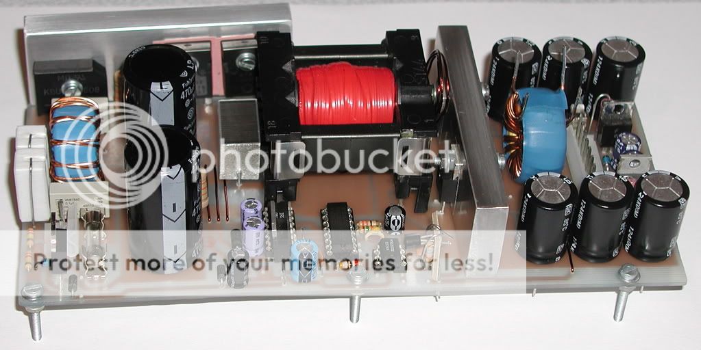
I have to wipe my screen off from drueling on it. That looks really professionally done! What are your main MOSFETs? Are you using the SG3525AN or the MC33025? I think you posted it, but I'm too lazy to go back and look (or I just don't want to scroll away from the picture of your PSU. 😉
Hi
Thanks, very much. I use SG3525, and main mosfets are Mtw 24n40e. But will use IRF450 next time, they should be good enough
Thanks, very much. I use SG3525, and main mosfets are Mtw 24n40e. But will use IRF450 next time, they should be good enough
luka said:Hi
Thanks, very much. I use SG3525, and main mosfets are Mtw 24n40e. But will use IRF450 next time, they should be good enough
is that etd 54 core ?
how did you make PCB ? You made or paid to be made?
Hi
I core is actually ETD44, biggest, but still small enough to get hight lower then 4cm (I hope)
Wouldn't be true diy if I didn't make everything myself. Yes I did pay, but only with my time. What do you mean "how did you make PCB". With program of course.
I core is actually ETD44, biggest, but still small enough to get hight lower then 4cm (I hope)
Wouldn't be true diy if I didn't make everything myself. Yes I did pay, but only with my time. What do you mean "how did you make PCB". With program of course.
luka said:Hi
I core is actually ETD44, biggest, but still small enough to get hight lower then 4cm (I hope)
Wouldn't be true diy if I didn't make everything myself. Yes I did pay, but only with my time. What do you mean "how did you make PCB". With program of course.
Did you pay for making pcb or you used ACID(H202+ HCl) and photo PCB for making it
- Home
- Amplifiers
- Power Supplies
- Offline full-bridge SMPS… need help