Hi
My amp is for now connected to push-pull, where I have bass pumping and I think that feedback is too slow. Also I have problem if supply voltage drops too much amp starts to put +vcc on output until there is current flowing to load. I will have to try to change cap that is used in supply for 4060 from 22uF to 100uF+. I think that amp becames unstable at some point.
What is your capacitance in your supply(toroid)?
I have huge secondary voltage drop under heavy load too, but this isn't a problem with regulated ones and not that big if you have high output voltage, like +/-90v. IRs are great for smps if I tell you from my experience. But I would like to try it with trafo too, so I think that is great idea.
Please do post your work, if you will have problems, here are a lot of people that can help you
stable supply
Luka
Post #575 has a URL that I will help in all area's of design and simulation of your supply, check it out it is a good read. But to answer your question first the secondary voltage should be at least twice the voltage for your load requirement so the supply can respond quickly to any demands, second it should be designed to stay in the CM by that the inductors should be sized correctly for the load and the filter cap's should be the correct value for the ripple you expect or desire then you will have an idea of the filter roll off and from that you can use Brown's book to design your feedback.
chas1
Hi
Because I think that voltage mode it better for smps that drives amps. I don't know what I would gain with use of current mode.
Because I think that voltage mode it better for smps that drives amps. I don't know what I would gain with use of current mode.
Why is it better? It does have a better dynamic response and for the higher power it does make sense.
Hi
Since this is my first offline smps, that I haven't even put in enclosure and power my amp with it, that why is VM.
CM have better dynamic response? What does that mean, like it can react to load change faster?
Since this is my first offline smps, that I haven't even put in enclosure and power my amp with it, that why is VM.
CM have better dynamic response? What does that mean, like it can react to load change faster?
I uploaded a short document, about Voltage-Mode and Current-Mode powersupplies. It writes advantages and disadvantages of both controlling methods:
http://sziget.mine.nu/~danko/aramkor/pdf/Current_Mode_vs_Voltage_Mode_Control.pdf
http://sziget.mine.nu/~danko/aramkor/pdf/Current_Mode_vs_Voltage_Mode_Control.pdf
current mode vs voltage mode control
Luka
The answer is contained in the pdf file posted by Danko, Amps are loads that can go into and out of CCM (the load current varies over a wide range) for this reason I would use voltage mode control. By using a current transformer in series with the primary you can still achieve a form of current control on a pulse by pulse basis.
chas1
Current mode has a better dynamic response and can react much faster to load transients.
Unitrode's design note lists the advantages and disadvantages but from what was mentioned regarding load requirements it appears that voltage mode may be of choice.
A trade off would be to design for current mode and add a ton of slope compensation. The more that you add the closer you are to voltage mode. This enables a fast response but it still handles well at low loads.
VM & CM
Luka
While I agree that current mode is the choice for new designs with the new controller IC's a well compensated voltage mode is the best for this application because the slope matching can be difficult with the noise level from any rail problems, again by using a filter cap with a small series resistor as the filter output ( a higher ripple should not be a concern) and you can obtain a 20db slope for a resonable fxo that will aid in the compensation and some DCM can be tolerated. check out the simulations at the URL I posted earlier it simulates the performance of a +/- 35 volt 10 amp two switch forward converter powering a half bridge classd amp.
chas1
Hi
That site is great, I've learned alot. Now I know that I my coupled inductor is 80uH, that is 4 times of a single winding. That does seems to be a bit to low, will increate it until next board to 200uH maybe 250.
About pummping effect it seems that I can't do much. There are two things I can do, first is to have lowest ESR possible, second is to have bigger output capacitance so that this effect will have to charge bigger C, resulting in lower increase of voltage.
Hi
The time has come.
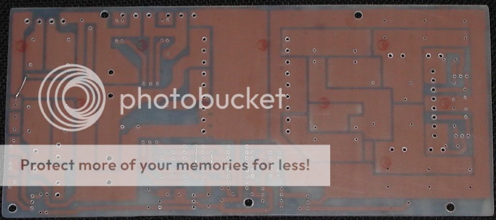
Made new board, which has a lot of new things on it that previous didn't have. This one should be easly good for 1kw, since old one did already give me 730w with 1kw peaks 🙂D ripple stuff)
Here are some pic of it


The time has come.
Made new board, which has a lot of new things on it that previous didn't have. This one should be easly good for 1kw, since old one did already give me 730w with 1kw peaks 🙂D ripple stuff)
Here are some pic of it
Hi Luka,
Very nice work on the pcb. Congratulations.
I just need to say that is very good for safety take care of the distance between tracks on mains side and output side (4mm or more) and other isolation questions.
regards,
Very nice work on the pcb. Congratulations.
I just need to say that is very good for safety take care of the distance between tracks on mains side and output side (4mm or more) and other isolation questions.
regards,
Hi
Thanks. About safety didn't take any care, because I think that 4mm is too much, would lose a lot of board space, although I could use narrower tracks, but don't know how wide to use them, for ~1kw smps, about 3-4mm I guess.
Thanks. About safety didn't take any care, because I think that 4mm is too much, would lose a lot of board space, although I could use narrower tracks, but don't know how wide to use them, for ~1kw smps, about 3-4mm I guess.
Luka,
I have to agree with blmn on 4mm, even though your design is not in large-scale production, and may not be subject to the 4mm gap required by many of the world's regulatory agencies. It's just a safety thing, since voltages on the primary side will be approaching 400VDC (higher if PFC'ed). 4mm was chosen because this was the minimum safe distance of the dielectric constant of even the most "conductive" (or least insulative) pc board materials (be it phenolic, fiberglass, whatever). Just a thought. Other than that, I like the 3-D space-claim rendition of it.
Steve
Hi Steve
I have too agree too, maybe I will fix this. When I look at 3D and the real board, there is no big difference just colors 😀, this will look to kill if you know what I mean, hopefully it will work even better then old one did, now I just have to get 35x35mm 1000uF/200v caps for primary, then hopefully won't be gigher then ~37mm with board.
I have too agree too, maybe I will fix this. When I look at 3D and the real board, there is no big difference just colors 😀, this will look to kill if you know what I mean, hopefully it will work even better then old one did, now I just have to get 35x35mm 1000uF/200v caps for primary, then hopefully won't be gigher then ~37mm with board.
Nice work, Luka.
How are you going to implement the output coupled inductor? On a toroid core? Can you provide some more details about its design?
Thanks!
How are you going to implement the output coupled inductor? On a toroid core? Can you provide some more details about its design?
Thanks!
Hi
Yes output inductor is coupled, on core size of T-102 I think it is, will took two wires, wind them in same direction on core, both in parrallel at the same time, then wind as much/right value of turns.
Then you, on one side cross wires so that you get both inductors add flux in core if current is going through both. Use "right hand" rule to see if you did that right. If you are going for unregulated don't use inductor at all. Hope that I did answer you good enough.
- Home
- Amplifiers
- Power Supplies
- Offline full-bridge SMPS… need help