Damn, sorry.Didn't check.It is reversed.
So that is what I use now.I'm only worried about primary waveform.
So that is what I use now.I'm only worried about primary waveform.
pix of supply
Jim
In case you question was for me, the supply is halfbridge, using igbt's and for the test I was doing the efficiency is about 78 %, you made reference to diodes in series with mosfets, do you mean gate , drain or source. In the gate drive I use a transformer driving a pair of emitter followers (sg3525 sources about 200ma) and to keep it happy I added the EF's. The secondary is connected in series with the gate thru a small resistor which is connected to the drain thru an RC filter.
chas1
does this help
Luka
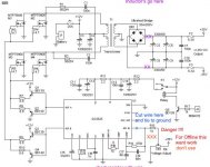
I am posting a pix which is not my circuit but one for the ESP website that should be close to yours even though the input is from car battery, the output is the important part. The violet x close to R16 is where you would short pin 2 to pin 16. This is only to clear up a setup for unregulated supply for testing. After you add the inductors and you compensation plus feedback you are all set.
chas1
Luka
I am posting a pix which is not my circuit but one for the ESP website that should be close to yours even though the input is from car battery, the output is the important part. The violet x close to R16 is where you would short pin 2 to pin 16. This is only to clear up a setup for unregulated supply for testing. After you add the inductors and you compensation plus feedback you are all set.
chas1
Attachments
Hi luka,
are you stuck with the transformer size and pinout?
Does the output connector have to sit on the very right side?
Because by changing any one of the two, you could either route in between the transformer center tap and the other winding by simply narrowing the center tap solder pad or just swap positions of transformer and capacitor bank.
If you can't do either, maybe rotating the transformer could help, but I'm not seeing the left part of the board. 🙂
2cents... 😉
Ciao,
Sebastian.
Hi,sek
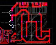
Trafo size is not a problem,it is what I have.Output connector: don't care where it is as long as it is on the right side of the board(at the end)
"swap positions of transformer and capacitor bank", I don't think that would be smart thing to do as the primary tracks would become longer.I would like to move only the connector up/down so I/you don't have many options.
Attachments
Routing
Luka
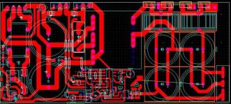
I am sure you thought about this but I don't see why this won't work. Maybe pcb size or whatever and remember it's not a crime when laying out single sided pcb's to use jumpers. When I get in a spot like this and I am doing a proto I have a roll of cooper tape and I place it on the topside drill holes where needed and connect with wire just like feed thru's. I posted a pix hope this helps. What size are your output caps they seem large to me? For the power you are using (around 400 watts) 2 1000uF on each rail should do, Check out Pressman and calculate the size of your caps with his method. Why are you using such a small pcb remember you have to test and work on the supply and also good air flow is necessary.
chas1
Luka
I am sure you thought about this but I don't see why this won't work. Maybe pcb size or whatever and remember it's not a crime when laying out single sided pcb's to use jumpers. When I get in a spot like this and I am doing a proto I have a roll of cooper tape and I place it on the topside drill holes where needed and connect with wire just like feed thru's. I posted a pix hope this helps. What size are your output caps they seem large to me? For the power you are using (around 400 watts) 2 1000uF on each rail should do, Check out Pressman and calculate the size of your caps with his method. Why are you using such a small pcb remember you have to test and work on the supply and also good air flow is necessary.
chas1
Attachments

caps in series
Jim
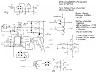
You asked about the photo of I guess my supply and there was a question about caps in series, It has dawned on me that the question might refer to the small cap in series with halfbridge transformer primary to prevent flux imbalance in winding during switching cycles. It would have been a wise choice since you save a part but I am planning to use this supply in current mode control so I placed a capacitor voltage divider across Vin (320VDC output of input caps) and tied the primary to the center. This offsets the need for extra windings on primary of transformer and diodes used in current mode control of halfbridge I've read about.The caps are 2.5uF 250 VAC polyester film. If it was voltage mode control I would have used a single 1uF cap in series with the primary. I have tested the supply for many hours monitoring the current waveform of the primary and there seems to be no flux walking and the temp is about 35 deg C in ambient air.
chas1
Jim
You asked about the photo of I guess my supply and there was a question about caps in series, It has dawned on me that the question might refer to the small cap in series with halfbridge transformer primary to prevent flux imbalance in winding during switching cycles. It would have been a wise choice since you save a part but I am planning to use this supply in current mode control so I placed a capacitor voltage divider across Vin (320VDC output of input caps) and tied the primary to the center. This offsets the need for extra windings on primary of transformer and diodes used in current mode control of halfbridge I've read about.The caps are 2.5uF 250 VAC polyester film. If it was voltage mode control I would have used a single 1uF cap in series with the primary. I have tested the supply for many hours monitoring the current waveform of the primary and there seems to be no flux walking and the temp is about 35 deg C in ambient air.
chas1
chas1,
i was looking at your post that you could go up to 1kw with your half bridge. isnt that a bit much? or have things changed in parts?
what is the dissipation of your igbts?
i have attache a couple of files diy.pdf is one i am building diy1.pdf is one isaw some where that uses diodes in the source of the high side and decoiupling across the fets.
what is your opinion??
i think we need to work on some multi kw stuff.....
jimbo
Attachments
diy
Jim
I looked at the fullbridge pdf files and I am posting a link to a-and-t labs website there you will find a 700 watt amplifier that includes a fullbridge power supply that is capable of 2kW peak and was design by Reinhard Metz who is a member of this forum. The design is proven and many post concerning it are in the forum. At this site you will find all doc's including schematics and pcb's along with all parts to construct this supply for about 300.00 bucks but the main idea for DIY is that the complete doc's along with the winding and construction tips are presented.
http://www.a-and-t-labs.com
chas1
a-t labs 700 watt power supply
i was looking at this and i was wondering what peoples thoughts were regarding no capacitors isolating the gate drive transformer on either the input or theoutput of the gate drive xfmr.
or why no zeners on the gate to source.
this seems to be a dparture from the app notes..
jimbo
i was looking at this and i was wondering what peoples thoughts were regarding no capacitors isolating the gate drive transformer on either the input or theoutput of the gate drive xfmr.
or why no zeners on the gate to source.
this seems to be a dparture from the app notes..
jimbo
Why using Full bridge?
Isnt better ot is it possible: USING half bridge wirh two irfp460 in PARALEL if you want higher currents more power ?
Isnt better ot is it possible: USING half bridge wirh two irfp460 in PARALEL if you want higher currents more power ?
a-t labs 700 watt power supply Post #298
i was looking at this and i was wondering what peoples thoughts were regarding no capacitors isolating the gate drive transformer on either the input or theoutput of the gate drive xfmr.
or why no zeners on the gate to source.
this seems to be a dparture from the app notes..
and..
no body diode bypass diodes, and a 1:1 output transformer....
what am I missing,.........
- Home
- Amplifiers
- Power Supplies
- Offline full-bridge SMPS… need help