Hello,
I have simulated a 2nd order Butterworth filter and I come with 2.6mH+20uF for 8ohm load and a cutoff of 700Hz.
Carrier attenuation at 30kHz is about the same with the original 4th order (at 4kHz cutoff) and with the 2nd order at 700Hz.
The peak-peak inductance ripple current with the 2nd order filter is 1.3A, which is good compared to the 8A of my original filter. The problem is that at full power I will have a low frequency peak current of about 190V/8R=24A and making a 2.6mH inductor capable of 24A without saturation asks for enormous core (roughly 6 times bigger than the actual one) or with air core, as you did.
I would like to avoid air core for space and possible EMI issues at that power level...
On top of that if the filter remains outside the feedback loop every change in inductance value due to saturation translates directly into THD.... air core will avoid this but I don't like it too much.
Any idea about my tough of keeping just the first section of the 4th order filter inside the feedback loop and make it self-oscillating?
Thank you
Any idea about my tough of keeping just the first section of the 4th order filter inside the feedback loop and make it self-oscillating?
Definitely better than building a giantic choke. However I would go higher with switching freq.
Generally you should not worry about residual output ripple too much:
I agree.
Hello,
I have done some calculations about the chokes and switching loss.
Increasing the frequency to 70kHz does impact the switching loss but it is still acceptable.
By doing this I have increased the filter cutoff at 6.4kHz and it is realized with a 185uH choke and a 6.8uF capacitor, just a 2nd order filter.
Carrier attenuation at 70kHz is now 48dB or about 2.7Vrms at speaker terminals at 70kHz.
The inductor will be realized with 88 turns on 2 stacked T225-2 cores, much more manageable than before.
Having a 2nd order filter allows me to do post filter feedback
thank you
ciao
-marco
low cutoff gives big coils, right.
my idea back then was to make the filter LC quite low-ohmic in relation to the load (-> smaller air choke, bigger oil capacitor) . The drawback is higher triangle current at the switching frequency even at zero output voltage. That and the fact that you must ensure under all circumstances that the LC does not get excited at the inherent resonance by the audio signal otherwise the semiconductors get too much current instantly.
I finally managed both drawbacks after some IGBT explosions.. There was just no way to increase the switching frequency above 25kHz using 1200V IGBTS back then.
At lower rail voltage with today's 600V semiconductors, I agree that there definitely is a case for choosing much higher frequency, e. g. 70 kHz or the like.
Hello everyone,
after about one year I have finished designing and building my amplifier.
The main differences with respect to to original project are:
1) Class-D stage is now UCD style running at 100kHz with 2nd order LPF
2) Power MOSFETs are Silicon Carbide Cree C3M0065090D (900V 65mR SiC)
3) Audio isolation is perfomed with HCPL7840.... very bad choice. It has an
output noise of 30mVrms (from datasheet) and this makes about 1.3Vrms at
the output.... It is a white noise generator, not an audio amplifier. I have
managed to limit the noise by filtering (subwoofer only amplifier) but
anyway the output noise is still to high. I should have used Pafi's solution
but now is too late.
I have set the dead time to 100ns; it is maybe too long but I would like to start on the safe side and then reduce it if needed.
I have started to work on it and after some values tweaking, mainly for idle switching frequency (100kHz) and gate resistors (SiC are really fast indeed) I was able to pull out 500Wrms @ 80Hz continuous from it with an efficiency above 90%.
Not yet done full power test because I have to build a 8R dummy load first to test it. Also the current limitation circuit is not been tested... I am a bit scary about doing it...
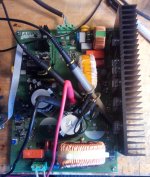
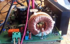
In attached you will find the complete schematics and some pictures of the assembled amplifier.
Comments and suggestions are welcome
ciao
-marco
after about one year I have finished designing and building my amplifier.
The main differences with respect to to original project are:
1) Class-D stage is now UCD style running at 100kHz with 2nd order LPF
2) Power MOSFETs are Silicon Carbide Cree C3M0065090D (900V 65mR SiC)
3) Audio isolation is perfomed with HCPL7840.... very bad choice. It has an
output noise of 30mVrms (from datasheet) and this makes about 1.3Vrms at
the output.... It is a white noise generator, not an audio amplifier. I have
managed to limit the noise by filtering (subwoofer only amplifier) but
anyway the output noise is still to high. I should have used Pafi's solution
but now is too late.
I have set the dead time to 100ns; it is maybe too long but I would like to start on the safe side and then reduce it if needed.
I have started to work on it and after some values tweaking, mainly for idle switching frequency (100kHz) and gate resistors (SiC are really fast indeed) I was able to pull out 500Wrms @ 80Hz continuous from it with an efficiency above 90%.
Not yet done full power test because I have to build a 8R dummy load first to test it. Also the current limitation circuit is not been tested... I am a bit scary about doing it...
In attached you will find the complete schematics and some pictures of the assembled amplifier.
Comments and suggestions are welcome
ciao
-marco
Attachments
Nice to see that you made it 🙂
Too bad that you got trapped by this pitfall.
Regarding isolation amplifiers you could also have a look to Analog Devices.
I.e. ADUM4190 is a low cost type which is approved for
reinforced insulation per CSA 60950-1-03 and IEC 60950-1,
for 400 V rms (565 V peak) maximum working voltage.
Test voltage also 5kV, like the HCPL.
60950 (IT&Office) and 60056 (Audio) have been harmonized some years ago, so a certification acc 60950 has gained weight also for audio applications. ...check with your certification institute... or if it is just for
DIY you can consider to trust that IT&Office should be as safe as audio (most likely you have already connected your IT-devices with your audio devices since 20 years...)
Output noise is less than 2mVrms or 5mVrms, depending which output you are chosing.
..and there are many more isolation amplifiers in the market. It's worth to spend some time for the search and check which one fits your taste best.
HCPL7840.... very bad choice. It has an
output noise of 30mVrms (from datasheet) and this makes about 1.3Vrms at the output.... It is a white noise generator, not an audio amplifier.
Too bad that you got trapped by this pitfall.
Regarding isolation amplifiers you could also have a look to Analog Devices.
I.e. ADUM4190 is a low cost type which is approved for
reinforced insulation per CSA 60950-1-03 and IEC 60950-1,
for 400 V rms (565 V peak) maximum working voltage.
Test voltage also 5kV, like the HCPL.
60950 (IT&Office) and 60056 (Audio) have been harmonized some years ago, so a certification acc 60950 has gained weight also for audio applications. ...check with your certification institute... or if it is just for
DIY you can consider to trust that IT&Office should be as safe as audio (most likely you have already connected your IT-devices with your audio devices since 20 years...)
Output noise is less than 2mVrms or 5mVrms, depending which output you are chosing.
..and there are many more isolation amplifiers in the market. It's worth to spend some time for the search and check which one fits your taste best.
One approach that I tried almost 20 years ago was to use a self oscillating half-bridge on the primary side of a high frequency 1:1 isolation transformer. A smaller winding on the same transformer provided control voltage. The audio was demodulated using a phase shifted synchronous rectifier. The difficulty is that the rectifier switches need to operate in all 4 quadrants.
I did this using 2 N-channel mosfets in series connection as D-S-S-D with the gates common and driven by a gate drive transformer. 4 of these switches are needed for full-bridge or 2 may be used if the transformer secondary is centre tapped. Because phase shift is used to demodulate, the gate drive transformers always operate at 50% duty cycle and a common driver and/or transformer may be used. I seem to recall the control circuit having a VCO to track incoming frequency and the error signal adjusting the phase.
Whilst I did get it to work it was not very reliable. I think there is a better chance these days with the mosfets now available.
The big advantage of course is that all the control circuit and audio input/output can all be ground referenced.

Hello everyone,
I have started to do some measurements on the amplifier and the results seems very good:
1) Output power on 8R load: measured 388Vpp at clipping, it is 2350Wrms
output power.... not bad. The green trace is the output voltage, the blue
trace is the output inductor current at 20A/div. I have made this test with
continuous sinewave for about 20seconds to measure the total efficiency.
Input power is 2492W with a power factor of 0.99. It is an efficiency of
about 94%.
2) PFC switching: ZVS is correct, switching frequency is 45kHz.
Purple trace is PFC IGBT Collector at 100V/div, Yellow trace is IGBT gate
at 5V/div, blue trace is ZVS MOSFET gate at 5V/div; this signal is very
noisy due to improper connection of the scope probe.
3) Tried some thermal test at about 1500W output, continuous sinewave,
after about 1h the heatsink stays at about 55°C... I think that it is way
overkill but I will keep it as it is...
Stay tuned for new updates
ciao
-marco
Attachments


Any hint about your PFC circuit?
Something like this?
https://de.scribd.com/document/2947...a-Boost-Converter-for-PFC-with-ZVS-and-or-ZCS
Something like this?
https://de.scribd.com/document/2947...a-Boost-Converter-for-PFC-with-ZVS-and-or-ZCS
- Home
- Amplifiers
- Class D
- Offline amplifier