M2 without degeneration
Hi there,
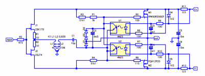
I think I have found a solution 🙂 Attached you will find a (admittedly amateurish) schematic of a modified M2 that has no source resistors. The power supply tabs V+ and V- are supposed to come form the main supply capacitors which are directly connected to the rectifier banks, just as shown in the NP design. Further I designed in different mosfets and an nice 1:7 microphone transformer (Sowter 4935).
I have not build this amplifier, but expect it to have more (>50% +) pure class A output with the same load. Also the performance may improve because of better supply 'regulation' (the filter resistors in the PS are effectively doubled). Finally the effectively available rail (AND output) voltage will be slightly higher with more or less equal supply (i.e. transformer, rectifiers, primary as well as secondary supply capacitors). Only the R in CRC has been doubled by me compared to the original Nelson Pass design. And the source degenerating resistors are left out of course 😀
cordial salute,
Mark
Hi there,
I think I have found a solution 🙂 Attached you will find a (admittedly amateurish) schematic of a modified M2 that has no source resistors. The power supply tabs V+ and V- are supposed to come form the main supply capacitors which are directly connected to the rectifier banks, just as shown in the NP design. Further I designed in different mosfets and an nice 1:7 microphone transformer (Sowter 4935).
I have not build this amplifier, but expect it to have more (>50% +) pure class A output with the same load. Also the performance may improve because of better supply 'regulation' (the filter resistors in the PS are effectively doubled). Finally the effectively available rail (AND output) voltage will be slightly higher with more or less equal supply (i.e. transformer, rectifiers, primary as well as secondary supply capacitors). Only the R in CRC has been doubled by me compared to the original Nelson Pass design. And the source degenerating resistors are left out of course 😀
cordial salute,
Mark
Attachments
1. xformer will perform better , if connected as autoformer
2. now to build , and compare is it sounding better than original ....... and does it work in real life (caps across these leds can be tricky)
2. now to build , and compare is it sounding better than original ....... and does it work in real life (caps across these leds can be tricky)
(caps across these leds can be tricky)
Can you expand, please?
I've built a M2 using Teabags boards, after an initial mistake I've rebuilt one channel with new components (other than the transformer and a couple of caps). One works but the rebuilt one doesn't, I get a constant hum/buzz when connected to a speaker that doesn't change when volume is increased, no music at all.
The other one works perfectly. I've checked for dry joints, tested for continuity and can bias it using the variable resistor. Any ideas as I'm starting to lose patience.....
The other one works perfectly. I've checked for dry joints, tested for continuity and can bias it using the variable resistor. Any ideas as I'm starting to lose patience.....
I've built a M2 using Teabags boards, after an initial mistake I've rebuilt one channel with new components (other than the transformer and a couple of caps). One works but the rebuilt one doesn't, I get a constant hum/buzz when connected to a speaker that doesn't change when volume is increased, no music at all.
The other one works perfectly. I've checked for dry joints, tested for continuity and can bias it using the variable resistor. Any ideas as I'm starting to lose patience.....
Have you checked voltages at certain test points and compared it to the working channel? That would be what I would attempt next.
Have you checked voltages at certain test points and compared it to the working channel? That would be what I would attempt next.
Any suggestions as to where?
It's more tricky than you might think.
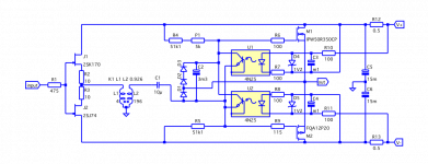
I realise this now... Still I believe attached schematic (improved from the one in post 1441) really works. Without degeneration. It should give near identical performance as the original M2. But it has more class A power available than the original at equal quiescent power.
Ironing out the power supply inrush currents to obtain an analogue of the "average" quiescent current takes some extra building blocks, such as the capacitors C3 and and C4.
caps across these leds can be tricky
...ehhh? I fail to see why, unless the time-constant were made excessively large (which I have not done).
Zen Mods remark on wiring the transformer as autoformer is valid. I think the modified M2 I propose will already be very, very nice with a mu metal core microphone transformer😀
enjoy your recordings!
Mark
Attachments
microphone ?
if they can handle that level o signal ..... remember that you need almost rail to rail swing capability
if they can handle that level o signal ..... remember that you need almost rail to rail swing capability
microphone ?
if they can handle that level o signal ..... remember that you need almost rail to rail swing capability
You're right. Up to 12 bBu input at maximally 0.5 % THD at 50 Hz, that is what the manufacturer promises for the 4935. You would reach the max level at approximately 30.5 Vp (at 50 Hz) at the transformer output.
But actually... I intend to use it only as amp for tweeters in a an active loudspeaker. In the upper octaves the distortion of such a x-former is really low😎
I realise this now... Still I believe attached schematic (improved from the one in post 1441) really works. Without degeneration. It should give near identical performance as the original M2. But it has more class A power available than the original at equal quiescent power.
...[snip]
Mark
Mark this is very nice and in case you need encouragement, you should know that many of us are watching from afar! I found great subjective improvements in my own amplifiers when eliminating the source R - i did it by simply bypassing with a cap - (your approach is much more cool). Some amps need a bit of tweaking of compensation if done that way, but the results are well worth it imo...
Despearse, check your +- inputs. They might be backwards.
Thanks, I'd checked already

Still I believe attached schematic (improved from the one in post 1441) really
works. Without degeneration. It should give near identical performance as the
original M2. But it has more class A power available than the original at equal
quiescent power.
Many DIYers like simple physical solutions to these problems.
By this I mean big heat sinks.
When you look at the bias drift on push-pull Mosfets without any
degeneration you will usually see a drift of about 50% up on bias from the
25 deg C figure up to case temperatures of 65 deg or so. The more heat
sinking you have, the less change in temperature, so the less drift.
If you set the bias and then sit there and re-adjust it as the temperature
climbs you will generally arrive at a stable value, and there you are.
The penalty besides having big heat sinks (how is that a penalty?)
is time. It takes time for the amplifier to warm up to the final bias figure
and it takes time to set the bias in the first place.
Time is something that manufacturers can't generally afford, but DIYers
have in abundance.
Maybe I'll expand on this a bit at BAF.
Thanks Zen Mod, measurements from the non functioning board are:
A = 108mV
B = -86mV
C = 8mV
R13 = 668mV
R14 = 665mV
1-2 = 1.07V
4-5 = 9.5V
And the working one measures:
A = 85mV
B = -65mV
C = 7mV
R13 = 668mV
R14 = 667mV
1-2 = 1.05V
4-5 = 9.6V
Next step is to remove the faulty board and check traces and transformer continuity
A = 108mV
B = -86mV
C = 8mV
R13 = 668mV
R14 = 665mV
1-2 = 1.07V
4-5 = 9.5V
And the working one measures:
A = 85mV
B = -65mV
C = 7mV
R13 = 668mV
R14 = 667mV
1-2 = 1.05V
4-5 = 9.6V
Next step is to remove the faulty board and check traces and transformer continuity
- Home
- Amplifiers
- Pass Labs
- Official M2 schematic