the amount of positive feedback in F7 seems only to be 2dB, review Absolute Sound,
And yours?
And yours?
the amount of positive feedback in F7 seems only to be 2dB, review Absolute Sound,
And yours?
Good question,how do I go about measuring that?
Oh I thought you measure your gain at the output….without the PSF and then you insert your 15k and you look how much more gain you have.
2dB are 1.258925x more signal than you had without.
Decibels to Voltage Gain and Loss convert calculation conversion amplification amplifier electronics - sengpielaudio Sengpiel Berlin
but the problem for me is that the F7 has less neg feedback and not no feedback.
The pos feedback in the F7 takes away a bit to the neg feedback, and in M2 you add to gain some more gain.
But I am not really informed….or competent.
Last edited:
Thanks for the tip, I will look into the F4 (and other F5, F6 balanced approaches) and see if I can come up with something, I will need time and advice...
it is possible , and question is all but stupid
edit : look at F4 for necessary buffer construction precautions
Oh I thought you measure your gain at the output….without the PSF and then you insert your 15k and you look how much more gain you have.
2dB are 1.258925x more signal than you had without.
Decibels to Voltage Gain and Loss convert calculation conversion amplification amplifier electronics - sengpielaudio Sengpiel Berlin
but the problem for me is that the F7 has less neg feedback and not no feedback.
The pos feedback in the F7 takes away a bit to the neg feedback, and in M2 you add to gain some more gain.
But I am not really informed….or competent.
OK here goes (no pfb) .84v in----3.861v no load-----3.753v 8 ohm load--- gain= 4.58 out z=0.23ohm damp factor 35
(pfb) with 1.5 ohm and 15k .84v in----3.172v no load----3.143v 8 ohm load
gain=3.83 out z=0.07 ohm damp factor 135
All at 1khz.
So what does it all mean ???? I'm just a back yard mechanic when it comes to this. Will I hear a difference of will I blow up something? Guess i'll try it and see
Hm, is there a reason that the pos feedback resistor connects after the magnifying element, the autoformer.
Normally I would say connect it in front f the autoformer.
Normally I would say connect it in front f the autoformer.
Oreo how have you selected the transformer values?
From Elliot Sound Literature
" ---For example, a transformer might claim to be -3dB at 30Hz with an impedance of 600 ohms. That means that the inductive reactance is equal to 600 ohms at 30Hz,"
L = XL / ( 2 * π * f ) Where XL is inductive reactance and f is frequency
L = 600 / 2 * π * 30 )
L = 1.59 H
From Edcor Data----Frequency Response 20~20K Hz., <1dBu
I just used the 20hz as the lower frequency in my calculation,its probably more like 5 hz for -3db. which would give about 20H.From there I tried different values for the other L that gave me a gain of 5,that value worked out to 100H. If 5hz was used then the values would be 20H and 500H.
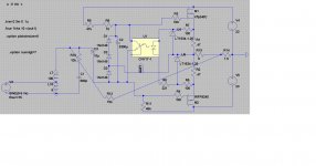
Here is my first attempt om a balanced M2-DCB1 combo, thanks to previous modeling posts and encouragement.
I found the Edcor settings on a .rs website with these parameters
Edcor PC600/15K (1:5)
pr. : 44Rdc, 240mH (600R)
sec. : 235Rdc, 5.7H (15k)
My trafos are already mounted so I can't measure them to verify, I hope they are correct, they model 1:5 voltage amplification fine.
I am still puzzled by the signal grounds in LTspice vs. no ground ref on a real balanced signal, and the volume control...
I made a complete working M2 SE model first, and than I simplified the M2 schematic and mirrored it with F5X signal input resistors. Next step would be a complete balanced model.
Any advice is welcome...
An externally hosted image should be here but it was not working when we last tested it.
An externally hosted image should be here but it was not working when we last tested it.
Here is my first attempt om a balanced M2-DCB1 combo, thanks to previous modeling posts and encouragement.
I found the Edcor settings on a .rs website with these parameters
Edcor PC600/15K (1:5)
pr. : 44Rdc, 240mH (600R)
sec. : 235Rdc, 5.7H (15k)
My trafos are already mounted so I can't measure them to verify, I hope they are correct, they model 1:5 voltage amplification fine.
I am still puzzled by the signal grounds in LTspice vs. no ground ref on a real balanced signal, and the volume control...
I made a complete working M2 SE model first, and than I simplified the M2 schematic and mirrored it with F5X signal input resistors. Next step would be a complete balanced model.
Any advice is welcome...
An externally hosted image should be here but it was not working when we last tested it.
An externally hosted image should be here but it was not working when we last tested it.
Thanks for the Edcor values.Boy was I off,so much for Elliot's calculations.
Don't remember the forum site/poster, but a guy also called Zen Mod was there... so thanks then!
I wonder , who measured that .........
I finished my M2 using TEA's boards but found it hard to adjust the offset at first but managed to get the offset spot on after increasing R7 to 51k.
Sound's very sweet on my Tannoy's.
Thank's TEA.
Steve.
Sound's very sweet on my Tannoy's.
Thank's TEA.
Steve.
I'v got a question.
What about separation power supplier and amp to different enclousers. Of course connection between them by external wire.
Could I place capacitors (15uF) in amp to ?
Please cons and pros 🙂
What about separation power supplier and amp to different enclousers. Of course connection between them by external wire.
Could I place capacitors (15uF) in amp to ?
Please cons and pros 🙂
- Home
- Amplifiers
- Pass Labs
- Official M2 schematic