The boards look very nice.
Thanks to Damian for supplying the boards.
Thanks to Peter for organizing the group buy.
Chris
Thanks to Damian for supplying the boards.
Thanks to Peter for organizing the group buy.
Chris
Thanks for veteran and aleph P1.7 GB
I receive my boards last week
in a perfect package
Thanks to Peter and Veteran
I receive my boards last week
in a perfect package
Thanks to Peter and Veteran
I would like to order 1 set of board if there are any left. Ideally gold plated but if none left, tin plated.
Thank you
Ludovic
Thank you
Ludovic
No idea if this is the correct place to mention this but as it may be relevant to Veteran's boards...
In short i had a problem with oscillation. It would only appear if in single-ended input mode gain is set to high, ie bypassing the 10k input series resistor. As soon as the dip switch for gain on the grounded input is turned - around 10MHz appear at the output. The same situation if a pot is connected to the input - on low volume settings it oscillates.
I first noticed that touching the amplifiying MOSFET's gate stops the oscillations dead. Cut down the fet's pins to the absolute minimum but nothing changed. Eventually had to raise the grid stopper to 1k and this fully sorted all problems. It might have some minor effect on hi-freq response; i still haven't measured it.
I realise that most people will not use it the way i do: with an output attenuator and gain set lower (which it simply has to be with a cd source) there is no problem whatsoever.
Still, i wonder if layout has anything at all to do with it but my build uses pretty generic parts and other than the long leads on the MOSFETs nothing looks suspicious. DC op points are of course all fine.
Ideas?
I've missed the GB, and it seems that I'm not alone...
If someone has an extra kit, or even an older Aleph P 1.7 board collecting dust, I'll be happy to buy it at a reasonable price.
thanks
Emanuele
If someone has an extra kit, or even an older Aleph P 1.7 board collecting dust, I'll be happy to buy it at a reasonable price.
thanks
Emanuele
Hi peterpan, Hi veteran
...I am also always "late to the show"...
If there are any boards left (over) I'd be glad to buy a stereo set...
_else_
Can we please have (yet) another group buy😀 😀 😀
Regards
Reinhold
...I am also always "late to the show"...
If there are any boards left (over) I'd be glad to buy a stereo set...
_else_
Can we please have (yet) another group buy😀 😀 😀
Regards
Reinhold
Someone was asking if Dale RN60s fit or not... yes, but they are tight. As you will note from the pics, a couple of them sit above the others. Hopefully this won't be a problem, but if you think it might be, let me know.
Some other images linked:
closer view of 1 channel
https://home.comcast.net/~youngc1/AP17_full1.JPG
the PSU
https://home.comcast.net/~youngc1/AP17_PSU.JPG
some coupling caps I bought:
Elna Cerafine 47uf/100V and Silmic II 10uf/100V
https://home.comcast.net/~youngc1/Elna.JPG
Nichicon Muse KZ 47uf/50V and 10uf/100V
https://home.comcast.net/~youngc1/Muse.JPG
Nichicon Muse ES 10uf/50V
https://home.comcast.net/~youngc1/Muse_ES.JPG
I'll also probably go with BlackGates eventually, but it looks like they will run around $45 USD or so... these were dirt cheap in comparison.
Also, since these are all polarized caps, is there any preferred direction for these to be put in? + towards input?
An externally hosted image should be here but it was not working when we last tested it.
Some other images linked:
closer view of 1 channel
https://home.comcast.net/~youngc1/AP17_full1.JPG
the PSU
https://home.comcast.net/~youngc1/AP17_PSU.JPG
some coupling caps I bought:
Elna Cerafine 47uf/100V and Silmic II 10uf/100V
https://home.comcast.net/~youngc1/Elna.JPG
Nichicon Muse KZ 47uf/50V and 10uf/100V
https://home.comcast.net/~youngc1/Muse.JPG
Nichicon Muse ES 10uf/50V
https://home.comcast.net/~youngc1/Muse_ES.JPG
I'll also probably go with BlackGates eventually, but it looks like they will run around $45 USD or so... these were dirt cheap in comparison.
Also, since these are all polarized caps, is there any preferred direction for these to be put in? + towards input?
Pars said:
Also, since these are all polarized caps, is there any preferred direction for these to be put in? + towards input?
Preferred direction? You mean how not to blow them?
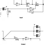
+ goes obviously towards the more positive: input gate is more positive (by about 12-13v) than input ground and output drain is about 30v more positive than output ground.
analog_sa said:
Preferred direction? You mean how not to blow them?
+ goes obviously towards the more positive: input gate is more positive (by about 12-13v) than input ground and output drain is about 30v more positive than output ground.
Yes, I guess. I've never done any amps that used coupling caps, and certainly not electrolytic. So, per the attached drawing, the positive should go towards the FETs in both instances?
Also, any resolution to your oscillation issue a few posts back? By grid stopper, were you referring to R6 and R13?
Thanks,
Chris
Attachments
- Status
- Not open for further replies.
- Home
- Group Buys
- Offical Details 2nd Aleph P1.7 Board GB