I ran 5 NOS RCA, and 3 NOS GE 6EW6 tubes through the test setup today. The RCA were similar to each other as were the GE's, but the two different brands were nowhere close to each other in the adjustments on plate voltage and cathode current needed to get minimum THD. None of the 6EW6's could get below 0.15%. I started testing a box full of used 6EW6's and each tube required some iterative tuning to get below 0.2% THD, so I gave up on them for now.Have you done any experimenting with a 6EW6?
I have been testing a box filled with about 1000 used 6AK5 tubes and have gone through over 100. Once I set the pots with a few NOS tubes, I never had to change them. I have 5 tubes that made less than 0.09% THD and my trash the tube threshold is 0.2%. So far, I have tossed two tubes that were above 0.5% THD, one that had gone to air, and one that lit up but did nothing. A whack with a screwdriver produced internal sparks, so something was loose inside. Again, the WE tubes had the lowest THD.
I haven't tried a cascoded CCS yet, so I can't say which is best. For now the current setup allows for variable gain which was intended for a guitar amp, and it requires only one mosfet. The circuit was designed for a super low cost guitar amp over 10 years ago. It does its job, so I keep using it.I’ve got very good results with 6J5P loaded with cascoded CCS.
That’s why I was asking the benefits of this bootstrapped gyrator compared to the cascoded CCS.

Is it a possible way, grounding the pmosfet source follower drain and gate, while setting the gain stage bias by changing the screen voltage? The Rds-on of the pmosfet must be high to do so, I think.
Low THD isn't wrong, but maybe not the only important parameter. Did you look at the harmonic spectra? Or did you maybe even use the board to drive a power amp and speakers with music to your ears?
That configuration makes triode-like curves, it is always second harmonic dominant, or at least this is how I set it.
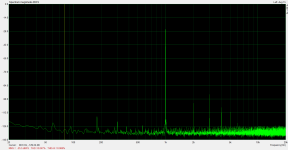
As stated, the THD is mostly second harmonic. The driver board has been tested with an UNSET based output board in SE with a single large TV sweep (line output) tube, a pair of the same tubes paralleled, and a 4D32 transmitting tube for a 20 watt, 40 watt and a 30 watt SE amp. Sound quality is excellent and a complete amp build using this tech is likely.Low THD isn't wrong, but maybe not the only important parameter. Did you look at the harmonic spectra? Or did you maybe even use the board to drive a power amp and speakers with music to your ears?
Attachments

I've done experiments with CCS-loaded pentodes with shunt feedback and my experience is that even with very large amounts of feedback, the output will be 2nd harmonic dominant until you get to a high enough signal level that you start approaching saturation and the positive supply (then you get compression on both ends and a rise in 3rd harmonic). Here are some measurements of a CCS-loaded EL34 with enough feedback to bring the gain down to 10V/V. This had a 1000V supply and 600V plate idle voltage, so 50Vrms out goes nowhere near the supply or saturation. Then I cranked it up and you can see 300Vrms out has a much more odd-harmonic content as we approach areas where the system does not behave as nicely.
The lesson I took from this is that as long as you pay attention to how you are treating your pentode, you don't have to fear its distortion harmonic character.
The other interesting thing is that even though I have made attempts to confirm it in tube circuits, I have never seen any evidence backing up the Baxandall graph that you sometimes see where adding feedback suppresses lower order harmonics and raises higher order harmonics (at first, which then can be suppressed by increasing feedback further). In my experience with tube circuits, all harmonics go down with increasing feedback.
Attachments

Hi George, nice circuit! Similar to the SCG preamp, which of course was inspired by your UNSET idea. I am wondering about a couple of things. One is whether you had a specific reason to take the feedback from the top of R2 as opposed to the bottom of R2 (referring to schematic in post 11), and two, whether using a depletion mode FET in the CCS would simplify the design. Thanks for sharing!
In this case the feedback takeoff point wouldn't make much difference since the feedback resistor is 1.8 megohms. The circuit created by mosfet M1 and the associated parts however is not a CCS. It has been somewhat incorrectly called a "gyrator" by some since it does exhibit most of the characteristics of an inductor, albeit with a rather high DCR. Its output is a constant VOLTAGE set by R14 and R17. I refer to this circuit as a bootstrapped load since a nearly perfect copy of the plate voltage appears on the top end of its load resistor, R2. This makes R2 appear quite large for AC signals. Any conductive path connected to the plate appears in parallel with this bootstrapped load, so R12 could affect the overall gain if it was a smaller value resistor. Since C2 and the R16, R14, R17 path to AC ground forms a high pass filter the overall response of the mosfet bootstrapped load begins to look like an inductor. This is why it is often called a gyrator.
I originally created this circuit for a low buck guitar amp designed for the Hundred Buck Amp Challenge thread which has become a sticky in the Instruments and Amps forum. The original circuit from 2015 is included. In that design the large gate resistor (R9 in the GTA schematic) was made a variable front panel control to allow for a wide range of gain at the twist of a knob.
The post #11 schematic also has an RC network from grid to ground that shunts some of the feedback to ground. I have experimented with making this a front panel control as well, but it's best used in the output stage of an UNSET based guitar amp as sort of a variable triode / pentode knob. As predicted the results vary greatly with the characteristics of the speaker load it's driving.
In this case the mosfet is just as follower so the choice of a depletion or enhancement mosfet will only change the plate voltage a few volts. The IXTP6N100D2 IS a depletion mode mosfet, but my test board has an enhancement mosfet in it. Real CCS circuits that use the source resistor to set the current level need a depletion mode mosfet...or a vacuum tube.
Back when you posted your SCG preamp I built one and experimented with a bigger version for use as an output stage with an IXTP6N100D2 driving a 600 ohm to 8 ohm output transformer intended for tube amps. I laid out a PCB for this amp, but never got any of them made. I'll get back to it once I'm done trying to reinvent the guitar amp. I'm still playing the little 4 tube amp I built in 2015.
Attachments
Wow, thank you! The gain adjust idea is so cool!
The way I understand the gyrator operation is that it keeps the load line perpendicular to the device operating point at all conditions, i.e., voltage swings, by adjusting the AC current in proportion to the signal on the plate. In other words, it keeps the load impedance high at all swings. With the depletion part, the bias is simplified but it provides the same type of operation (or it seems that way to me anyway). It does not, however, provide an easy way to continuously vary how much it gyrates, if you will, which is a very neat way to adjust gain. Nelson has another way to adjust the gyration fraction by splitting the source resistor into multiple parts and taking the output from between the resistors. You can adjust the amount of AC feedback that way.
The way I understand the gyrator operation is that it keeps the load line perpendicular to the device operating point at all conditions, i.e., voltage swings, by adjusting the AC current in proportion to the signal on the plate. In other words, it keeps the load impedance high at all swings. With the depletion part, the bias is simplified but it provides the same type of operation (or it seems that way to me anyway). It does not, however, provide an easy way to continuously vary how much it gyrates, if you will, which is a very neat way to adjust gain. Nelson has another way to adjust the gyration fraction by splitting the source resistor into multiple parts and taking the output from between the resistors. You can adjust the amount of AC feedback that way.
@Tubelab_com
I have some question regarding R2:
Its value is bootstrapped by 1/(1-Av) that should mean between 50 and 100 times.
The anode is limited in swing by the lower voltage the anode can reach (around 40-50 V) and on the upper side by the voltage set by the gyrator minus the voltage drop across R2.
For a driver, I would consider 5 to 10 mA (depending on the capacitance and the needed swing of the “driven”) to guarantee the full swing at full bandwidth.
10 mA and 33 kOhm means losing 330 V on the available swing.
On the opposite side, 5 mA and 10 kOhm means losing only 50 V of swing.
How do you target the available swing compared to the needed swing for the output tube? I’ve read some prefer to have twice the needed swing on the driver to improve the recovery after the overload.
Thanks,
Roberto
Is it the same with your ccs loaded pentode driving a triode then applying gnfb?I've done experiments with CCS-loaded pentodes with shunt feedback and my experience is that even with very large amounts of feedback, the output will be 2nd harmonic dominant
Nearly always, yes. Sometimes the system is third-harmonic dominant. I think this is because certain output tubes have about the same amount of 2nd harmonic distortion as the driver does, and since they are opposite phase, they almost cancel each other out, leaving third harmonic to dominate.
Edit: Any time I have gotten a dominant 3rd spectrum, the distortion was always extremely low.
Edit: Any time I have gotten a dominant 3rd spectrum, the distortion was always extremely low.
The tube amp l want to build right now is an:
‘It’s UNSET, guaranteed’ 🤣
I became a real aficionado of the tubelab approach. It works and works well!
‘It’s UNSET, guaranteed’ 🤣
I became a real aficionado of the tubelab approach. It works and works well!
@Tubelab_com @SpreadSpectrum
The gyrator as a load fixed the voltage at the source of the mosfet.
Can then use it to dc couple the driver to the UNSET output tube (GU50 need around 15-20% lnfb to become linear), and so set its bias?
With a FETSET driver, can we bias the driver by referring the gate to ground (so again dc coupled to the source) and set the bias by using a negative supply for the drain of the pmosfet source follower? This would help going closer to 0V (a tube would not swing down to few volts, fet can swing to 4-6V more than the pmosfet drain) on the base of the pmosfet, reaching full power.
In any case, ac coupling the infeed and dc ciupling driver and output stage is better than the opposite, having more swing in the latter.
What am I missing?
- Home
- Amplifiers
- Tubes / Valves
- Of course it will work, it's guaranteed!