I don't understand.
0.25uF is no longer a standard value, unlike 0.22uf and 0.33uF
30 seconds at the Digikey website produced these results for film capacitors:
0.22uF 2178 choices
0.33uF 1872 choices
0.25uF 26 choices
My point was that in a feedback amplifier you don't change the coupling cap values by 50% just because they "are no longer available," without making other adjustments in the circuit. Substituting a .27 for a .25 is within an acceptable 10% deviation and probably won't have any significant effect on the design.
Yep, he did make a substantial change.
Capacitors, Resistors and Schematics for Tube Radios / Electronics
Ah, you do not know about fine suppliers such as Just Radios. I have been buying from them for more than 10 years. There web site is:I don't understand.
0.25uF is no longer a standard value, unlike 0.22uf and 0.33uF
30 seconds at the Digikey website produced these results for film capacitors:
0.22uF 2178 choices
0.33uF 1872 choices
0.25uF 26 choices
Capacitors, Resistors and Schematics for Tube Radios / Electronics
Last edited:
Unfortunately, websites like that link in post #33 can generate an 'allure' to thinking that any vintage amplifier can be easily updated with modern parts.
Sadly that can be a very expensive and stressful experience for those taking on the Williamson circuit, and could leave some exiting this diy hobby from frustration.
Hopefully the OP will endure - it certainly seems that that will be the case. Although it is difficult for someone new to hi-fi valve amps to continue through the process of wiring up and achieving an operating amp, and then appreciate that it has to really be tested for unconditional stability otherwise the amp may cause collatoral damage. Some Williamson variant kits during the 1950's became notorious for being tweeter killers, and I'd suggest that some may nowadays cause woofer damage (as experienced by the OP).
And being hi-fi, it can be saddening to think that the amp sounds superb, only to someday do a measurement and find it distorting well beyond what the original circuit should do. Luckily, nowadays a diyer can so easily test distortion and hum from their amp, compared to the 1950's when that was out of the question for all but electronics professionals with appropriate lab gear.
Last edited:
No need to worry, it is interesting and I appreciate the opportunity to learn new things. I know I could spend far less to buy a modern Class D amplifier, but that would not look right with the nice 1951 (or 1952) Browning Laboratories tuner.
Strictly speaking a pole is a special point in the complex plane description of a filter. It is also used as a shorthand for corner frequency i.e. the point where the filter begins to have a sigificant effect on signal amplitude. If you do any reading about filters you will quickly see lots of poles!FStephenMasek said:So a "pole" is kind of a barrier or threshold, kind of a soft low pass or high pass filter? I'd never read the term "pole" before now.
Your assumption is incorrect. I used to recommend justradios- probably ordered 10 times from them over a period of 10 years or so- but my last order wasn't filled, emails weren't answered, and I had to get my money back via PayPal. There never was any follow-up from Dave Cantelon (JustRadios). So it would be a good idea to make sure communications were working before submitting an order.Ah, you do not know about fine suppliers such as Just Radios. I have been buying from them for more than 10 years. There (sic) web site is:
Capacitors, Resistors and Schematics for Tube Radios / Electronics
Indeed, that comment about 0.25 capacitors being hard to find was humorous, as was his comment about using a 5U4G because it is still in production while the other rectifier tube is only available NOS. His site states that he was a broadcast engineer. I like the way he drew his schematic. I do see that most of the designs include some sort of balancing control, so I will have one in Version II of the amplifier.
can we have the link to the site please?
Unfortunately, websites like that link in post #33 can generate an 'allure' to thinking that any vintage amplifier can be easily updated with modern parts.
I cannot agree more. Furthermore components have tolerances (capacitors often up to 20%). Get the wrong combination of 'worst' ones, and without test instruments, you are in for midnight oil.
Few extra comments:
1. I notice frequent use of directly heated rectifiers. Yes, the ubiquitous 5U4 has its place, but places unnecessary high voltages at certain points before the other tubes have heated to emission.
E.g. see the concertina phase splitter: Before the 1at triode and the phase splitter itself have heated up, there is some 450V potential between g1 and cathode - not sure how safe that be! Then should the phase splitter heat up somewhat faster than the first triode, current flows from cathode to grid, etc. The 5AR4/GZ34 is quite more suitable.
2. There appears to be a certain reticence to use large decoupling caps. Good quality electrolytic caps are small and affordable these days; there should be little quibble to using 68µF to >100µF. (I have a 100W stereo tube circuit where I have to insure stability with four l.f. time constants in the main NFB loop!)
3. I notice the 47K driver anode load resistors are closely specified - but the next stage grid resistors of 100K not. These are in parallel and should be of equally low spread!
4. The well-known 807 just never dies! No problem, but as an r.f. tube it might be desirable to put 100 ohm to 220 ohm stopper resistors in their screen circuits. (My favourite is the 6L6GC.)
5. I am uncertain, but long ago the measure of using large value decoupling caps over the cathode resistors was advocated to give a semblance of fixed bias operation with signal, with audible increase in signal output at lower distortion. I have occasionally done that advantageously - but ir might be dependent on the rest of the circuit filter time constants for stability.
It is working better than ever with the changes shown on the schematic below. Would you reduce the value of the resistors feeding the 6SN7 plates to increase the voltage? It is already louder than needed. The bass seems better with these changes.
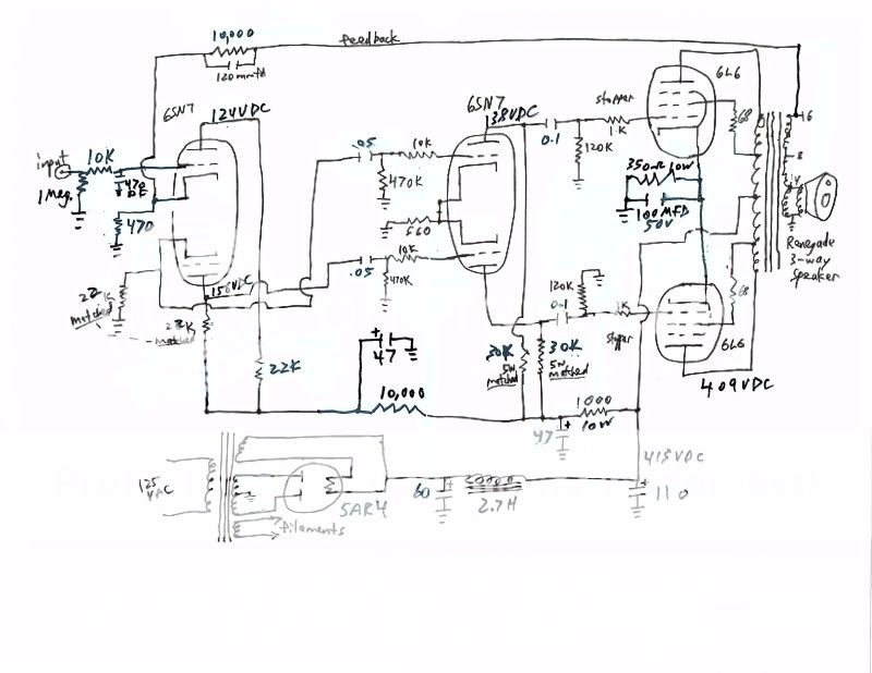

If anything I would resort to the original values of 47K. The entire circuit will compensate for the lower B+. You don't need the 10K grid resistors to the 6SN7 grids, I'm not sure why they're there. I would also implement the cathode/grid balancing arrangement in the original, it will improve the balance of the output tubes and possible improve the bass even further. It can also help prevent current hogging by stabilizing the output tubes. Williamson designs have quite a bit of gain, there's really nothing you can about that.
I'm glad it's working and sounding better.
I'm glad it's working and sounding better.
You're not seeing much DC voltage across the phase splitter valve. Might get a better result by increasing the first stage's anode load to 47K or so. Direct coupled stages are always a balancing act.
If you want higher anode voltages on the push-pull drivers' anodes, you can adjust their common cathode resistor up a little, somewhere less than double should do it. Personally, I'd keep their grid stops - can't hurt.
All good fortune,
Chris
If you want higher anode voltages on the push-pull drivers' anodes, you can adjust their common cathode resistor up a little, somewhere less than double should do it. Personally, I'd keep their grid stops - can't hurt.
All good fortune,
Chris
Thanks for looking and studying. How does in reading the resistor increase, rather than decrease, the voltage? I measured all of the voltages to ground.
Increasing a cathode bias resistor tends to increase the valve's bias (grid negative compared to cathode), so anode current decreases, so voltage dropped across anode load resistor decreases, so anode voltage rises. Like that.How does in reading the resistor increase, rather than decrease, the voltage?
All good fortune,
Chris
Interesting!
Of course, my $1,400 "smart" phone changed "increase" to "in reading".....
I went back and re-measured the voltages on the 2nd 6SN7 plates. With no input, I found one at 181VDC and the other at 222VDC, both measured to ground. I re-checked the 30,000 ohm resistors and they are well-matched. Perhaps I need a balancing rheostat?
One of my output tubes is a 6L6GB, the others 6L6GC, so I may also need to procure a better match.
Last edited:
Interesting!
Of course, my $1,400 "smart" phone changed "increase" to "in reading".....
I went back and re-measured the voltages on the 2nd 6SN7 plates. With no input, I found one at 181VDC and the other at 222VDC, both measured to ground. I re-checked the 30,000 ohm resistors and they are well-matched. Perhaps I need a balancing rheostat?
One of my output tubes is a 6L6GB, the others 6L6GC, so I may also need to procure a better match.
I agree with Chris that the first 6SN7 plate resistor should be changed back to 47K. Who keeps making the changes to your schematic--and why? Nothing wrong with experimenting, but there's a perfectly well-vetted schematic to follow in the Hafler/Keroes article. You don't have the same output transformer so you're going to have to be careful about some of the components, especially the small cap across the feedback resistor, which is *always* tuned to a specific transformer using a scope.
As for the 6SN7 driver imbalance, two possibilities:
1) Your 6SN7 has very poorly matched plates. Try a couple different 6SN7s.
2) If the problem persists, in my experience it's a sign of oscillation. Try disconnecting the feedback resistor/cap and see if the imbalance goes away. If it does, you have oscillation. Try reconnecting the feedback without the cap across the feedback resistor. If they stay pretty much balanced (within 5 or 6 volts) then you will need to apply a scope to adjust that cap to improve square wave response and eliminate HF oscillation, or leave it off and hope for the best. ;-)
Also, a 6L6GB is not going to be happy for long in that amp. They are rated for only 19W dissipation and weren't made for this kind of service. And you currently have no way of knowing if the output tubes are balanced or not.
Hope this helps.
Last edited:
I tested the 6SN7 with my Hickok mutual conductance tester, and the plates are the same, so oscillation seems to be the problem. Time to bring out my oscilloscope. I may also try a variable capacitor in that feedback circuit to see what it does with different values.
- Home
- Amplifiers
- Tubes / Valves
- Occasional low frequency problem