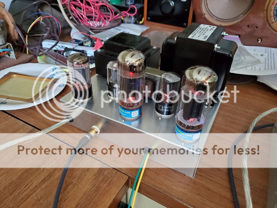
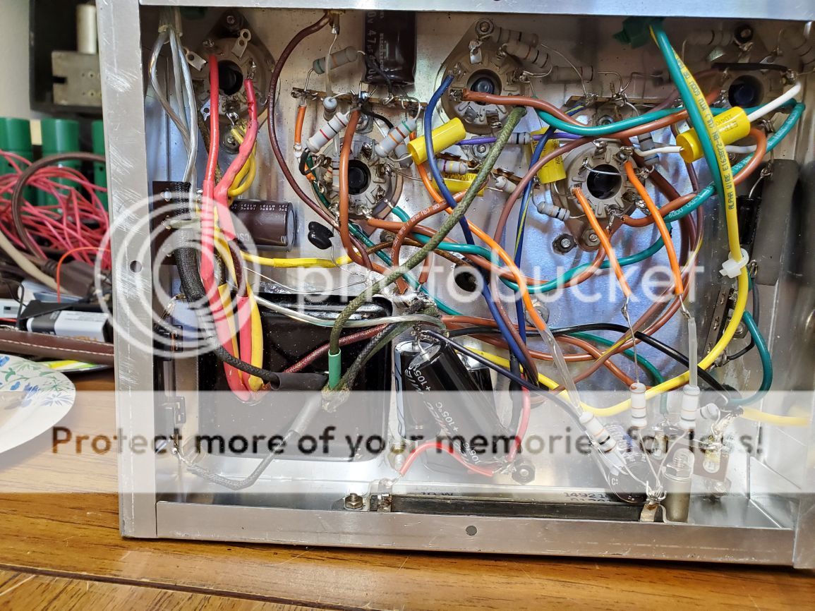
Check the value of the NFB capacitor.
I once had a weird oscillation around 1.2MHz that was cured by changing a 1000pf cap to 560pf.
It was weird in that it caused a voltage / bias shift but the amp worked fine otherwise.
I once had a weird oscillation around 1.2MHz that was cured by changing a 1000pf cap to 560pf.
It was weird in that it caused a voltage / bias shift but the amp worked fine otherwise.
FStephenMasek,
Your schematic in post # 53 . . .
The input 6SN7, bottom triode has a floating grid.
Where is the grid connected to?
How about a 1k grid stopper from that floating grid to the plate of the top triode?
Your schematic in post # 53 . . .
The input 6SN7, bottom triode has a floating grid.
Where is the grid connected to?
How about a 1k grid stopper from that floating grid to the plate of the top triode?
Last edited:
Oops, that grid connects to the plate of the input triode. I reprinted and edited an earlier scan of the schematic on which I'd forgotten that connection.
Even though my (calibrated) Hickok mutual conductance tube tester showed both plates the same, I swapped the 6SN7 tubes and now have equal voltages on the plates of the 6SN7 which drives the 6L6 tubes. Strange.... I do not see any cold solder joints or other reasons to explain the change. Both 6SN7 tubes were New Old Stock. The tube sockets were brand new. I will have some brand new 6L6GC tubes tomorrow. and continue testing once I install them.
It is louder without the negative feedback, but sounds better with it connected. The small capacitor across the negative feedback resistor did not seem to make any difference. I tried using a variable capacitor. For now, there is just the resistor.
Distortion increases the perception of loudness. Gain makes it actually louder, unless you carefully adjust the volume control to compensate. Feedback reduces distortion and gain.
The Hickok checks one triode at a time. Right?
The measurements of plate voltages are independent (do not have any common influence from one triode to the other).
You want to solve why the tube tester showed matched triodes, but there were un-balanced plate voltages in the amp. Right?
Your amp driver stage has a common 560 Ohm cathode resistor for the two 6SN7 triodes.
That is DC feedback (common influence).
One 6SN7 has un-balanced plate voltages.
The other 6SN7 has balanced plate voltages.
Surprise! (not really).
Try removing the 560 Ohm common cathode resistor.
Then, connect each cathode through its own individual 1k Ohm self bias resistor.
Then, see which 6SN7 has matched plate voltages (I bet the un-balanced one is now much more balanced than it was before).
Right?
Now, connect the two 1k resistors and two cathodes together (I bet the 6SN7 that had un-balanced plate voltages is unbalanced again). Right?
(common influence of an imperfectly matched pair of triodes)
Now, use whatever cathode biasing you want, a common 560 Ohm.
Or individual 1k Ohms (but be sure to bypass the individual 1k Ohms with a individual bypass capacitors).
As one of my long time friend and former co-worker says: "attention to details".
Last edited:
We collected 600 sets of test data on multiple good-used, and multiple good-NOS 6SN7 tubes.
Before the other tests were begun, grid current was tested, if there was significant grid current those tubes were rejected.
When the individual triodes had very nearly identical voltages across the cathode self bias resistors, then the next test was that the tubes individual self bias resistors were connected together (and therefore the cathodes were connected together).
At that test of common cathodes, there often were un-balanced results.
I am just saying.
Last edited:
I tested 14 vintage used (but ok) 6SN7 in Williamson circuit, with no output stage valves fitted, and measured the driver stage performance - anode voltages; 2nd harmonic dist on output stage grid leak for each side; voltage gain at output of each side - all at 10Vrms signal level on anode of one side, and all with 6.0Vrms heater.
There was noticeable variation of anode dc levels, distortion levels, and gains. Distortion ranged from 0.2 to 0.4%; voltage gain from about 15 to 18; only 2 samples had an anode dc voltage imbalance exceeding 8V (so they were suspect).
The main outcome was that in-amp valve rolling tests of available valves can be done and can provide confidence that an ok valve is being used, and test comparisons can go beyond what can be done on a valve tester.
please,try an 6p3S-e quad !I got it playing nicely now, with 6L6GB tubes.
best price/quality sound rapport for me
One of the 6L6GB tubes I had in it was producing some violet/blue glow, so I replaced it with the one 6L6GC I have, then played it for a few hours. The new 6L6GCs should come today.
One place selling 6p3S-e tubes shows the anode voltage as just 250, more3 like a plain 6L6GT. Why would you suggest using those in this amplifier?
One place selling 6p3S-e tubes shows the anode voltage as just 250, more3 like a plain 6L6GT. Why would you suggest using those in this amplifier?
That renegade speaker is also decent, especially given the low price, about $25 each. When I want more, I've got the Magnepan MG-IIIA speakers I bought in 1984...Good, glad it's playing good music!
One of the 6L6GB tubes I had in it was producing some violet/blue glow, so I replaced it with the one 6L6GC I have, then played it for a few hours. The new 6L6GCs should come today.
One place selling 6p3S-e tubes shows the anode voltage as just 250, more3 like a plain 6L6GT. Why would you suggest using those in this amplifier?
Russian very conservative datasheet.
I use every day two quad 6p3s-e around 400vdc
in fixed and cathode bias.
it's a great tube! and not expensive.
there are some serious sellers who sell on ebay with real pair well matched
One place selling 6p3S-e tubes shows the anode voltage as just 250, more3 like a plain 6L6GT. Why would you suggest using those in this amplifier?
Please note that the 250V anode voltage indicated was for typical operation. It was not a maximum spec.
But Oh Boy, when googling in a honest effort to help with maximum ratings ... what a confusing lot of 'information'! And nowhere on any Russian datasheet maximum anode/screen voltages were indicated; it was difficult enough to get even anode dissipation 😡
As several commentators said, a 'maximum' of 250V is simply ridiculous. One possibly reliable poster said maxima were Va = 400V, Vg2 = 250V. The fact that several guitar amplifiers are running them at >400V is no indication either.But although I have never actually seen one, as said there should be little reason why they should not at least equal 5881 ratings. Another quite plausible explanation was that while tubes have been ruggedized datasheets did not keep up; old data was simply repeated.
Thus sadly unable to find reliable information ... what a world ...
[P.S: I had the privilege to have at work a Dutch colleague who previously at Philips, Eindhoven, was actually in charge of writing/testing tube specs. He mentioned that where tubes could be used for r.f. service, the maximum anode voltages included such, i.e. taking into account internal/in-base discharge/sparking. In that sense anode voltages could be safely exceeded for l.f. work.]
and says a single 8 ohm tap will work "without upsetting the feedback arrangement." Well, no, it won't--it will reduce the feedback considerably.
The feedback is going to be affected depending on speaker loads anyway. I updated the circuit to adjust for available parts. It's not a good application of negative feedback going from output to the first input tube. At high volume when the output starts to saturate it then feeds a distorted signal back to the input. The phase inversion circuit pretty much forces you to go back to the input stage. I took that site down late 2019. After experimenting with single ended Class A I've become a Class A person.
But Oh Boy, when googling in a honest effort to help with maximum ratings ... what a confusing lot of 'information'! And nowhere on any Russian datasheet maximum anode/screen voltages were indicated; it was difficult enough to get even anode dissipation 😡
Thus sadly unable to find reliable information ... what a world ...
Who says that ? russian datasheets always show max specs, even the short form slip for the 6p3s does, and not difficult to find at all ... https://frank.pocnet.net/sheets/084/6/6P3S.pdf
it clearly says (2nd block of data halfway down the page):
heater voltage 7.0v max
heater voltage 5.7v min
anode voltage 400v max
screen voltage 300v max
cathode-heater voltage 200v max
anode dissipation 20.5W max
screen dissipation 2.75W max (the 22.75 is obviously a typo 🙂
grid leak resistor 0.5Mohm max
Attachments
Last edited:
- Home
- Amplifiers
- Tubes / Valves
- Occasional low frequency problem


