I wouldn´t mess with wildly unsuitable transformers, which tolerate NO DC at all and have insufficient "primary" inductance
I couldn´t care less about "math tricks" showing I can get "high primary impedance" just squaring voltage ratio and choosing a low voltage secondary IF that primary impedance will be shunted by such low inductance that it starts dropping below 500Hz or something.
Same thing with 70V transformers (or even 100V ones)
What´s the point of selecting, say, a 0.5W secondary and load it with 8 or 16 ohms so primary looks good, if again primary is shunted by a too low inductor?
Or to see it from a different point of view: 70/100V transformers are designed for 70/100VAC.
But a typical tube amplifier fed 450V +B runs some 600V RMS plate to plate.
Understood. You have the reputation of your company to maintain, you have warantees you have to stand behind, and your customers expect you to use quality parts in your products. And, you have the ability to make your own transformers as needed for your products, so you have no reason to try experiments with cheap OTs from improbable sources!I wouldn´t mess with wildly unsuitable transformers
Those of us who DIY guitar amps for ourselves don't have the same burdens, and we can afford to play a little. Sometimes this leads to nothing, but not always!
Which of these categories does this particular idea (100V audio line transformers repurposed as audio line transformers) fall into? Useless, or a surprisingly good solution to an increasingly difficult and expensive problem?
The whole idea of using 100V audio line transformers as valve amp OTs seems to have originated with a very smart gentleman named Paul Cambie: http://home.alphalink.com.au/~cambie/6AN8amp/M1115.htm
Not content with just coining the idea, Cambie built a push-pull valve Hi-Fi amp using EL84s for the output and a 6AN8 triode-pentode for the input and phase-splitter stages. He used the Altronics M1115 100 V audio line transformer as the OT. And like any good tech, he took careful measurements of his results, including some frequency response measurements. And what did he find?
With an 8 ohm dummy load at the output, he set his signal level to produce 12.6 Vpp (2.5 W RMS@ 8 ohms) at 1 kHz, arbitrarily chosen as 0 dB. Then he measured power output at various frequencies.
His amplifier measured (-1.5 dB) at 40 Hz, and (-2.7 dB) at 40 kHz - with NO overall negative feedback! 😱 Link: Construction
Cambie repeated his measurements, this time with a hefty dose of global negative feedback around the amp, and a very slightly lower voltage of 9.8 Vpp across the 8 ohm dummy load at 1 kHz. This time he obtained a response flat within +/- 0.2 dB from 40 Hz to 100 kHz!
The power supply Cambie built for this amp put out a B+ of 397 VDC un-loaded. More details here: Power Supply Considerations
So here we have solid data showing that a cheap 100V audio line transformer, used in a push-pull EL84 amp, with a B+ of about 400 volts, measured at an output power of 2.5 W RMS, had a frequency response flat from 40 Hz to 40 kHz.
This is heady stuff, for those of us who cannot build our own transformers, and instead have to save up $50 for a Hammond OT. (Quadruple that for New Zealand and Australia.) The cheap little audio line transformer turned out to be anything but junk: it produced results that are fairly respectable for valve Hi-Fi, and more than good enough for a guitar amp.
Okay, the little Altronics M1115 works very well at 2.5 W RMS. What happens at higher power levels?
There is an interesting 'Web page by the late Roly Roeper, describing some of his measurements. The same "15W" Altronics M1115 was pushed to produce 16 W RMS (just clipping) across an 8 ohm load at 1 kHz. After an hour, the core temperature rose to 65 deg C. Too hot?
Roeper repeated the test with an Altronics M1120, rated for 20 watts. At the same 16 W RMS output power, this one stabilized at 54 degrees C after one hour.
Here's Roly's page: Cheap Output Transformers
Then we have Tubelab George's data. He pushed a "10 W" transformer to 37 W RMS - nearly 400% of its rating. Not only did the transformer not burst into flames, it produced a response down only 4 dB at 82 Hz even while suffering this extreme overload.
Agreed. Math by itself only offers a good reason to investigate further. But Cambie measured, not just calculated - and he found the power bandwidth of his M1115 went down to 40 Hz @2.5 W RMS output using pp EL84s and 400V B+!I couldn´t care less about "math tricks" showing I can get "high primary impedance" just squaring voltage ratio and choosing a low voltage secondary IF that primary impedance will be shunted by such low inductance that it starts dropping below 500Hz or something.
Very true. I would not have dared to use a 400 volt supply on a 100V transformer...but Cambie and Roeper both did, and the transformer passed with flying colours. 😱But a typical tube amplifier fed 450V +B runs some 600V RMS plate to plate.
Now you can see why I'm still interested. For the Australian Altronics M1115 / M1120 transformer, there is just enough measured data out there to confirm that the idea really does work much better than anyone expected. Not just on paper, but in actual valve amps.
Sadly, I haven't found any similar data for the 70.7 V transformers we can find here in North America, at Parts Express and similar vendors. Are these Chinese-manufactured small audio line transformers as good as the Altronics line? We just don't know.
-Gnobuddy
M1115 primary inductance seems to be circa 12H. I'm about to buy one of these, so will try and get some L versus signal voltage measurements and some indication of V-f that can be supported.
Well, IF primary inductance is high, it will definitely work.
Just do the Math yourself, paralleling 12H with whatever impedance your tube needs.
Another interesting experiment would be to measure primary inductance when passing realistic idle currents through, say 50mA or whatever your power tube needs.
PS: you made me remember Roly 🙁
Just do the Math yourself, paralleling 12H with whatever impedance your tube needs.
Another interesting experiment would be to measure primary inductance when passing realistic idle currents through, say 50mA or whatever your power tube needs.
PS: you made me remember Roly 🙁
I made a set of measurements a few years ago for a good quality Red Line AF5 push-pull transformer with increasing DC bias - a noticeable drop off in inductance.
The M1115 is being used for PP and UL PP applications, as it has a fortunate set of taps.
Doh - measurement at end of linked doc:
https://www.dalmura.com.au/static/Choke%20measurement.pdf
The M1115 is being used for PP and UL PP applications, as it has a fortunate set of taps.
Doh - measurement at end of linked doc:
https://www.dalmura.com.au/static/Choke%20measurement.pdf
The amp Cambie built used EL84s, rated for 12 watt dissipation and 300 volts on the data sheets. So up to 40 mA quiescent current, worst case, per EL84. But he used a PP pair, so negligible net magnetization current in the OT.Another interesting experiment would be to measure primary inductance when passing realistic idle currents through, say 50mA or whatever your power tube needs.
Reading through Cambie's description one more time, I realized I had missed something: he wired his output stage in ultra-linear mode.
UL drops the output impedance at the anode a lot, so his OT was being driven by relatively low impedance at the EL84 anodes, much lower than we would see in a normal guitar amp. This is surely part of the reason he got to less than 40 Hz without the response falling by 3 dB.
I remember him with sadness too. 🙁PS: you made me remember Roly 🙁
Living on opposite sides of the planet, I never had the chance to meet him. I would have loved to have had that opportunity. His posts on AGGH were one of the reasons why I joined that forum some years ago.
-Gnobuddy
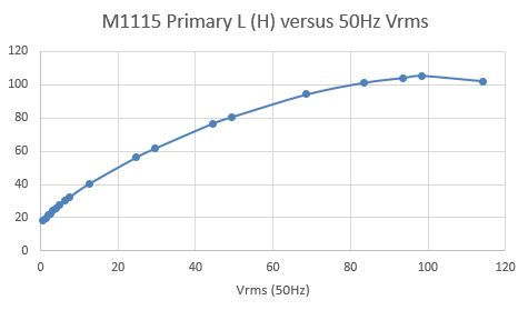
Well the plot below about accounts for reasonable performance of the M1115 100V line transformer with 8 ohm secondary. I'll try and go beyond that asap.
Primary is full winding from COM to 1.25W tap, with DCR=206 ohm.
Push pull configuration is COM to 5W tap to 1.25W tap, with DCR = 71 + 136 ohm (so a little imbalanced).
Primary is full winding from COM to 1.25W tap, with DCR=206 ohm.
Push pull configuration is COM to 5W tap to 1.25W tap, with DCR = 71 + 136 ohm (so a little imbalanced).
Last edited:
I'm confused. Inductance climbs as you drive more current through the transformer by increasing Vrms? 😕 And tops out at over 100 Henries? 😱
Wouldn't we expect L to fall as Vrms increases and the core begins to be pushed into lower-mu regions of the BH curve?
Or am I mis-reading your graph somehow?
-Gnobuddy
The 'average' permeability of a core (with sinewave AC voltage excitation) will increase with peak flux level, and reach a maxima, before falling as the peak of the flux swing extends more in to the saturation part of the core BH curve region. Depending on lamination material, the coil impedance generally has a max level when flux is 0.4-0.7 Tesla, and designers often set a max flux of about 1.2 to 1.5 T (higher for GOSS), although for hi-fi OPTs the peak flux is often kept below 1T to constrain increasing distortion.
The 15W rating of the M1115 relates to about 350Vrms across the primary, where the turns ratio is 31.6 : 1 for its 8 ohm secondary. Ie. 15W output to 8 ohm load is 11Vrms, and that is provided when primary is 31.6 x 11 = 350Vrms. 350Vrms may not be supportable at 50Hz, as the flux peak may be well in to saturation region, and current draw may be peaking quite high (not that that can occur in a valve amp) - I will see if I can take some current waveforms as primary voltage rises, to indicate what low frequency level can be supported.
The 15W rating of the M1115 relates to about 350Vrms across the primary, where the turns ratio is 31.6 : 1 for its 8 ohm secondary. Ie. 15W output to 8 ohm load is 11Vrms, and that is provided when primary is 31.6 x 11 = 350Vrms. 350Vrms may not be supportable at 50Hz, as the flux peak may be well in to saturation region, and current draw may be peaking quite high (not that that can occur in a valve amp) - I will see if I can take some current waveforms as primary voltage rises, to indicate what low frequency level can be supported.
Last edited:
Thanks, I didn't know that. I always feel that transformers are one of the elements of electronics that I never entirely grokked. (RF transmission lines, striplines, and microstrips are another.)The 'average' permeability of a core (with sinewave AC voltage excitation) will increase with peak flux level, and reach a maxima
Interesting. Roughly 1000 Vpp, meaning 500 Vpp at each output anode. Which in turn is about what you'd get with 300 volts B+ at full drive, assuming 50 volts lost to B+ droop and the "knee voltage" of the output valves.The 15W rating of the M1115 relates to about 350Vrms across the primary
I'm curious what the optimal valves to use with a transformer like the M1115 might be. Relatively high voltage / low current types with relatively high B+, limited by the audio line transformer's flashover limit? Or relatively low voltage / high current types (sweep tubes, 50C5 and family, etc) with lower B+, limited by the transformer's core saturation characteristics?
-Gnobuddy
In a PP stage, 350Vrms from plate to plate is 250V peak from either plate to CT.
The nominal primary impedance is 8k for push-pull with 8 ohm secondary, so that is the starting point.
Both Grant Wills and Frank Hughes showed 17W clean max level in to 8 ohm resistive load with 270-300V B+ in a fixed bias, UL configuration, so that's a good start for the M1115 with 6CM5. I'm hoping to repeat that setup soon, and will try and get some power-bandwidth and distortion info for both non-UL and UL configuration.
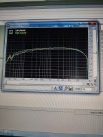
This is a 12W6GT triode wired push-pull using the Altronics M1120. No gNFB. About -1 dB at 40Hz and 20kHz. I have not yet researched the reason for the difference between left/right channel. Works surprisingly well.
Attachments
- Home
- Live Sound
- Instruments and Amps
- O/P Transformer DC Resistance Check