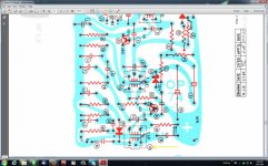
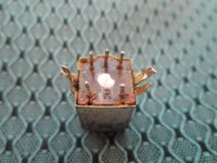
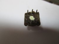
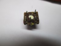
Where in the world can I get another one of these 455kc/s IF coil/transformers for a vintage AM radio? The parts list says it is Number 3 out of 3 of them on the board.The two pins on the bottom of the middle photo pins 4 & 5 aren't getting continuity so I tried to take it apart to see if I could fix it? The broken slug was the result of me trying to force it out of the can.
Attachments
Last edited:
There are places in the USA like Antique Electronics Supply and Radio Daze. I don;t know what is on your side of the earth, but I might start with a google search for "antique radio parts". I spotted an antique radio forum while I was doing that, that might be a better sort of forum to ask.
This type of thing used to be made by Toko (and others). It looks like the 3rd IFT feeds the diode AM detector. In the UK I would try JAB or Cricklewood Electronics.
Thanks fellas,I'm hoping to get one in Oz but I'm happy to know I can at least get one,so I'm off to ebay to try my luck.
With some care and attention, it is probably possible to rescue the original part: the broken wire can be fixed, and so can the broken slug.
The magnetic parts are made of iron powder dispersed in a binder, and adding a few micrometers here and there doesn't change the properties of the core very much. If you glue the broken parts together, the assembly will work very nearly like the original, except a slightly lower permeability which should easily be compensated for by a realignment of the IF strip.
Use a very minimal amount of cyanoacrylate glue, and keep the parts very strongly pressed together for quite some time: with this type of material, the setting time can be much longer than with ordinary stuff.
Be careful not to make any more damage during disassembly/reassembly
In the Netherlands, logical places to look for something like this would be Radio Twenthe in the Hague, the vintage radio forum Nederlands Forum over Oude Radio's and the quarterly fairs of the NVHR, the Dutch historical radio society.
In Australia, there is a similar organisation called Historical Radio Society of Australia. I don't know anything about it, except that it has a journal called Radio Waves.
If I were you, I would first try Elvee's advice and if it doesn't work out, see if I could contact the Historical Radio Society of Australia.
Or maybe take one from yet another old radio.
I thought of that actually,I have another vintage radio to restore but I don't want to cannibalise it because Ill have to get one for that eventually.
With some care and attention, it is probably possible to rescue the original part: the broken wire can be fixed, and so can the broken slug.
The magnetic parts are made of iron powder dispersed in a binder, and adding a few micrometers here and there doesn't change the properties of the core very much. If you glue the broken parts together, the assembly will work very nearly like the original, except a slightly lower permeability which should easily be compensated for by a realignment of the IF strip.
Use a very minimal amount of cyanoacrylate glue, and keep the parts very strongly pressed together for quite some time: with this type of material, the setting time can be much longer than with ordinary stuff.
Be careful not to make any more damage during disassembly/reassembly
I was very careful when I tried to disassemble it to start with and it only made it worse it seems to be welded in the can with eons of grunge and refuses to budge?
I was very careful when I tried to disassemble it to start with and it only made it worse it seems to be welded in the can with eons of grunge and refuses to budge?
A gentle heating perhaps?
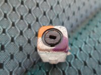
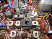
I tried heating it but still no go.I found some of these things in an old tape player but the problem is which one do I use? I have absolutely no idea about these things except that the one Ive broken is a 455ksc IF coil. Does one of these in the photo match that? The writing on the closest coil of the group of 4 at the top is A1 203.
Attachments
Last edited:
Looking at the transformers they might look similar but there are different grades of ferrite for different purposes.
OK the windings will be completely different and you will have to rewind your transformer but the core material may also be very different.
OK the windings will be completely different and you will have to rewind your transformer but the core material may also be very different.
Looking at the transformers they might look similar but there are different grades of ferrite for different purposes.
OK the windings will be completely different and you will have to rewind your transformer but the core material may also be very different.
Oh! I thought because the tape player was AM,FM,& shortwave, one of the AM coils would do the job? It looks like Ive got a lot to learn about tuners.Its pretty overwhelming when you have no idea to start with Ive sent out about 6 emails and Ive got about 3 replies that say sorry no go,dont have them.😕
Oh! I thought because the tape player was AM,FM,& shortwave, one of the AM coils would do the job?
Oh, you didn't mention that in your post.
An AM/FM set will have two sets of IF transformers, 455 KHz and 10.7 MHz. You would have to identify which is which and even then it may not work due to pinout differences. If you could get hold of the service manual for each set it would be a big help.
Oh, you didn't mention that in your post.
An AM/FM set will have two sets of IF transformers, 455 KHz and 10.7 MHz. You would have to identify which is which and even then it may not work due to pinout differences. If you could get hold of the service manual for each set it would be a big help.
The pin out for the coils looks pretty close on the National Panasonic RQ-546FJS tape player but I cant find a schematic for it? I finally got the original coil dismantled with some more gentle heat but because I know nothing about these things I ended up breaking another wire,so Ive got no continuity on both ends now. LOL So I'm going to have a go at gluing and soldering the impossible.😀
Attachments
The pins will be on a standard grid, but there is no standardisation for the function of each pin (even within one manufacturer's range). You will need to measure, reverse-engineer etc. I fear this may require knowledge, experience and test equipment you may lack.
The pins will be on a standard grid, but there is no standardisation for the function of each pin (even within one manufacturer's range). You will need to measure, reverse-engineer etc. I fear this may require knowledge, experience and test equipment you may lack.
Well Ive got an oscilloscope and a signal generator.From what I can work out its just a standard 455khz coil the third of a set in an AM tuning circuit? Why cant I just get one of them?
The pinout is quite standard: the 3 in a row are the resonant circuit: middle pin goes to the collector of a transistor, one end to + supply (they are usually Ge PNP transistor radios), sometimes there is a few hundred pF capacitor between the two ends, internally built in the case. The other 2 pins are coupled to the base of the next transistor, one end being GND. There might be small deviations from this, but most IF transformers are interchangeable. You should have continuity between the 3 pins on one side, and continuity between the 2 pins on the other side. See also this:
Radio Hobby Replacement 455 kHz If Transformers | eBay
Radio Hobby Replacement 455 kHz If Transformers | eBay
The pinout is quite standard: the 3 in a row are the resonant circuit: middle pin goes to the collector of a transistor, one end to + supply (they are usually Ge PNP transistor radios), sometimes there is a few hundred pF capacitor between the two ends, internally built in the case. The other 2 pins are coupled to the base of the next transistor, one end being GND. There might be small deviations from this, but most IF transformers are interchangeable. You should have continuity between the 3 pins on one side, and continuity between the 2 pins on the other side. See also this:
Radio Hobby Replacement 455 kHz If Transformers | eBay
Those ones on ebay are only $2 but they want $24 for postage so Ill give that a miss.Are these coils in a set all wound differently,so that I can replace say number 1,number 2,3,4,etc...? On the schematic it says that,this one giving me trouble is number 3.
- Status
- Not open for further replies.
- Home
- Design & Build
- Parts
- Number 3 455kcs IF transformer ?