How many people recognize the HP-67 calculator?
Nothing beats calculation in RPN ( Reverse Polish Notation). Same as we did with a slide rule, pencil & paper, from the inside of the equation & out. No equals sign, no brackets to get screwed up with. After running with RPN. I'd never go back.🙂
But did a lot of programming in BASIC anyway. On a HP 71B, got two of them.😀
Attachments

I just use statistical logic - capture 5-10 waveforms and look for variation of the initial peak current, and use the max observed as a good indicator.the proper way to measure the initial current would require a way of switching on the supply at the point where the current would be the maximum. I’ve no way to do that, never built something to make it happen.
Nothing beats calculation in RPN ( Reverse Polish Notation). Same as we did with a slide rule, pencil & paper, from the inside of the equation & out. No equals sign, no brackets to get screwed up with. After running with RPN. I'd never go back.🙂
But did a lot of programming in BASIC anyway. On a HP 71B, got two of them.😀
Am finding it relaxing to work with my old slide rule.
Attachments

I love my HP-11 RPN calculator.
I hope it never wears out (I got it in 1985)
And I still have my Post Versalog slide rule.
I hope it never wears out (I got it in 1985)
And I still have my Post Versalog slide rule.
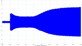
OK 20 to 20, Current vs time plots. But these are on the PT primary where we would normally install a current limiter..... So we see the initial high current drift down as the tubes warm up. When the tubes begin conducting at about 20 seconds the current to the PT increases. Just as we would expect.......
As Tim R has pointed out, the proper way to measure the initial current would require a way of switching on the supply at the point where the current would be the maximum.
I don't believe it would be necessary in trying to understand the initial current loads for practical purposes to have a plot begin on a 0v point. We can use the peak and the cold heater resistance to approximate a real maximum. Then the fun starts as the heater begins to change resistance with heat. The excersize in plotting the current is surely complex without setting up with just a single tube to test with and a regulated voltage source that wouldn't sag at startup. It would be interesting to know how many cycles it takes for the heater to increase its resistance enough to let the PT overcome any voltage sag that would also be a current limiter as such during startup. So the full amp cold heater load and the stoutness of the winding and primary /secondary efficiency for good regulation would be an issue for each individual amp. But what most people don't understand about these limiters is that if they are subjected to a rated load then they do their limiting in about .1 second and they are done. 6 cycles, average. The question then becomes how has the heater resistance changed in that period and was the heater actually buffered positvely by the limiter considering the sag that may also be a factor in the heater voltage duing that period. After a lot of years of reading posts from all levels of DIYers it's obvious that those adding current limiters to protect their PS components or tube heaters are wasting their efforts and money and just following the crowd and doing customization for the fun and novelty, or also lower the paranoia level they may have for whaterver reason. The tube heaters were designed to withstand cold starts and people can't be convinced of that, even with nearly zero reports of heater failures ever posted.
Last edited:
At one stage I had to design an acceptance test for incandescent bulbs for traffic lights. Switch something like 7500 lightbulbs on for 15 seconds then off for 15 seconds and check how long they'll last.
Then for giggles we did the same with a smaller bunch for 1 minute, IIRC it took about 6 weeks before they started to fail. At the same time we had another same sized bunch that used a small NTC in series. The latter bunch was still going after 6 months by which time we stopped the test. (The 1 minute was selected to give the NTC's time to cool down.)
Unfortunately NTC's for incandescent lightbulbs in traffic lights are not practical. In time LED's solved the problem of failed lightbulbs in traffic lights but by then I was long gone.
NTC's make a difference.
Last edited:
@EL506 -- there is a big current surge in the Phillips and Feit LED replacement bulbs when they are turned on. You can get a real surprise if you try screwing one in while the line is powered on!
Attached my current HP41 -- I think the iPhone app was $7. I've gone through 2 HP41's since the early 1980s.
Attached my current HP41 -- I think the iPhone app was $7. I've gone through 2 HP41's since the early 1980s.
Attachments

Often on a datasheet are remarks for a life expectancy of minimum 2000 times switched on or e.g. not more than 12 times / day. To me this indicates that there is a finite life expectancy for the filament.
Most damage to the cathode emission is done when the tube starts conducting but the filament has not fully heated up. There are remarks in the tube manuals of not applying HT to a rectifier until the filament has heated up - in other words if only implementing a slow start for the filaments but not for the HT then you may actually shorten the life expectancy.
Most damage to the cathode emission is done when the tube starts conducting but the filament has not fully heated up. There are remarks in the tube manuals of not applying HT to a rectifier until the filament has heated up - in other words if only implementing a slow start for the filaments but not for the HT then you may actually shorten the life expectancy.
Last edited:
....
Attached my current HP41 -- I think the iPhone app was $7. I've gone through 2 HP41's since the early 1980s.
Had one of those, loaned it to my daughter never to be seen again.
You forgot to mention that an incandescent light filament operates at a much higher filament temperature during normal operation, and that thermal transfer is only by radiation - that significantly changes the start-up conditions enough to render the light bulb example as having a poor (if any) relationship to extending the service life of a vacuum tube due to reduced heater failure rate.NTC's make a difference.
1. Leave an incandescent bulb on all the time, and it does not have to go through all those thermally caused expansions and contractions (one cause of failures).
2. I think the reduced life of an incandescent light bulb goes according to the 5th power of the increased power mains voltage.
A 110V incandescent bulb that is run at 120V:
110/120 = 0.917 (to more places most slide rule operators eyes will accurately go).
5 (Log 0.917) = - 0.188
10 ^ (-0.188) = 0.648 (Life reduced to only 64.8%).
That is why those 'long life' incandescent bulbs were rated for 130V to run on customers 120V power mains. The tradeoff is lower lumens, and Very warm color output (But some of those bulbs had blue colored glass to make the color balance cooler, the tradeoff was even lower lumens out.
Last edited:
The exposed part of the filament on some tubes light up like a flash bulb when powered on. Then when the rest of the filament (that is enclosed by the cathode) heats up the color of the exposed part becomes less bright.
Not so much of a difference as one might initially suspect.
Not so much of a difference as one might initially suspect.
I read the proffered issue as an NTC can extend the service life of a bogey valve due to lowered stress on the heater, but I can only see that as a warm fuzzy feeling in the belly for those who fit an NTC based on aiming for that outcome (ie. an extended service life).
I haven't seen datasheets for commonly used audio valves that identify a reduction in service life due to turn-on events, so would welcome some links.
The only related statistical data I've come across is for a special application back in the mid-1950's where they added an NTC and could confirm a benefit, but that application was significantly different enough to not be directly related imho.
Another Test With & Without Current Limiting
This test was with the same setup as the 8W amp using the Workman TV plug
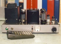
inline limiter. This time the amp is something I built two of circa 1960. 2X6L6GC UL PP, nominally 25W. The front end is a 6AU6 driving into a 12AU7, both sections paralleled in a split load phase inverter. There is DC stabilization of the front end thru a 12AU7 cathode back to 6AU6 screen connexion. I did a comparison to the regular hookup a few years ago. Just ask. The rectifier is a 5AR4. The OPTs is an obscure Japanese build, they even came with a frequency response test plot. The PTs are Hammond (naturally) 273BXs.🙂
There are both AC & DC Balance adjustments & bias setting. And the audio front end is somewhat protected from large LF transients by a 2-section Hi-Pass network.😀
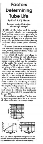
And a note to us from the good Prof AVJ Martin on tube life expectancy.
This test was with the same setup as the 8W amp using the Workman TV plug
inline limiter. This time the amp is something I built two of circa 1960. 2X6L6GC UL PP, nominally 25W. The front end is a 6AU6 driving into a 12AU7, both sections paralleled in a split load phase inverter. There is DC stabilization of the front end thru a 12AU7 cathode back to 6AU6 screen connexion. I did a comparison to the regular hookup a few years ago. Just ask. The rectifier is a 5AR4. The OPTs is an obscure Japanese build, they even came with a frequency response test plot. The PTs are Hammond (naturally) 273BXs.🙂
There are both AC & DC Balance adjustments & bias setting. And the audio front end is somewhat protected from large LF transients by a 2-section Hi-Pass network.😀
And a note to us from the good Prof AVJ Martin on tube life expectancy.
Attachments
-
 25W Amp Front.jpg74.9 KB · Views: 125
 -
 20211122-0003 25W Amp w Current Limiting.jpg62.7 KB · Views: 149
 -
 20211122-0002 25W Amp wo Current Limiting.jpg59.8 KB · Views: 149
 -
 Factors Detemining Tube Life B.jpg279.5 KB · Views: 136
 -
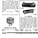 Surgistors & Workman Tube Guard Essco Catologue 1968.jpg251 KB · Views: 135
I read the proffered issue as an NTC can extend the service life of a bogey valve due to lowered stress on the heater, but I can only see that as a warm fuzzy feeling in the belly for those who fit an NTC based on aiming for that outcome (ie. an extended service life).
I haven't seen datasheets for commonly used audio valves that identify a reduction in service life due to turn-on events, so would welcome some links.
The only related statistical data I've come across is for a special application back in the mid-1950's where they added an NTC and could confirm a benefit, but that application was significantly different enough to not be directly related imho.
GEC KT66: Life performance
Tomer 1960, Getting the most out of vacuum tubes: e.g. page 150
Philips, ECC81, 82 etc: In case of serries supply a current limiting device must be inserted in the heater circuit for limiting the current when switching on
Last edited:
Ta, I do recall the GEC datasheet now - however it does not indicate what proportion of part failures were from a failed heater or other thermal cycling related faults like leaking seals or joints.
Tomer is a worry as the context of that section of the book relates to equipment with many tubes and a concern that thermal cycling of the equipment incurs faults. He doesn't quantify his 'experimental data' or provide even an example reference, or relate heater faults in a statistical manner to something practical like intermittent event numbers and operating life, which makes it difficult to indicate whether someone would see some % of their tubes fail due to heater turn-on events compared to other failure event statistics.
Tomer is a worry as the context of that section of the book relates to equipment with many tubes and a concern that thermal cycling of the equipment incurs faults. He doesn't quantify his 'experimental data' or provide even an example reference, or relate heater faults in a statistical manner to something practical like intermittent event numbers and operating life, which makes it difficult to indicate whether someone would see some % of their tubes fail due to heater turn-on events compared to other failure event statistics.
Tomer was very well known afaik, its just that that book was likely written for as wide an audience as practical.
The testing I tried hard to get a handle on was by Gano and Sandy (https://www.dalmura.com.au/static/Thermistors%20for%20the%20gradual%20application%20of%20heater%20voltage.pdf). MIT tried to minimise valve stress and failures in early valve computers such as the 'Whirlwind 1'. The only known reference to valve heater filament failure statistics related to turn-on stress. Gano did his Master's working on Project Whirlwind 1, and then continued to work on power coordination with Lincoln Labs. Thermistors for filament cycling was a project by Sandy starting in 1955. Two relevant reports are from 9 and 23 Sept and 4 Nov 1955 biweekly reports in Dome Home.
That heater powering setup did not use a typical mains isolation transformer, so may have been a lower impedance supply.
My recollection of the heater supply on the IBM 604 was a saturable reactor controlled by a 6L6. The 604 was an early electronic calculator, it could add, subtract, multiply & divide. But in BCD, not Binary. The big advance was Division, previous calculators did not have that ability. All in & out on 80 column punched cards. At that time IBM did not sell their equipment, everything was leased or rented. Depending on their needs the customer could run the 604 with 900 to 1500 6J6 flip-flops. It would heat a small house but it did the work of an Acre of girls cranking adding machines.😀
Thomas J Watson the CEO of IBM in those daze is on record as commenting the World would never need more than a dozen computers.🙂
Thomas J Watson the CEO of IBM in those daze is on record as commenting the World would never need more than a dozen computers.🙂
On current limiting heaters. I am feeding the heaters of a tube from a switching floating regulator (it's a high voltage amp and one tube heater moves several kVs).
I need to limit the inrush current and it works fine with a small 2.5R NTC from Ametherm (thanks Jackinnj).
But in operation, that NTC uses up about 10% of the total heater circuit power, which I hate.
Does anybody have an idea for a circuit that shorts the NTC after some time (or after the heater voltage is close to nominal) and NOT uses a relay?
Jan
- Home
- Amplifiers
- Tubes / Valves
- NTC Thermistor As Soft Start For Tubes