Sounds like you are having fun 🙂
......
Hello and i swear the last question ....
As i am thinking to use for V1 two 12V SLA batteries in series that when charged are around 13.5V for a total of V1= 27 V (already simulated and it is ok) how can i understand how much current the circuit will draw ? 🙄
I would not like to have to recharge them very often ... 🙁
Do you think that the idea is sane ?
or better a 30V PS kit ? and which one ?
Thanks a lot , gino
post65 working.
still getting 0.018% rather than 0.013%
Quite slow to get all 80ms into the simulation.
I'll pick up on post73 tomorrow.
still getting 0.018% rather than 0.013%
Quite slow to get all 80ms into the simulation.
I'll pick up on post73 tomorrow.
Last edited:
The main current consumption is the two collector currents of the transistors and the bias resistors.Hello and i swear the last question ....
As i am thinking to use for V1 two 12V SLA batteries in series that when charged are around 13.5V for a total of V1= 27 V (already simulated and it is ok) how can i understand how much current the circuit will draw ? 🙄
I would not like to have to recharge them very often ... 🙁
Do you think that the idea is sane ?
or better a 30V PS kit ? and which one ?
Thanks a lot , gino
probe the currents and add them up.
Or look at the DC op and run and look up the Ic of the two transistors.
I see 4.3mA & 0.3mA and R1 @ 0.4mA
total ~5mA
A 1Ahr battery will last ~ 200hrs, less it's own leakage, i.e. about a week
The main current consumption is the two collector currents of the transistors and the bias resistors.
probe the currents and add them up.
Or look at the DC op and run and look up the Ic of the two transistors.
I see 4.3mA & 0.3mA and R1 @ 0.4mA
total ~5mA
A 1Ahr battery will last ~ 200hrs, less it's own leakage, i.e. about a week
Thank you very much indeed ! so it is a viable solution
It is much easier to buy to batteries than to build a low noise PS
I have seen some nice 2Ahr for not much
I am curious to listen
And i know that i have to place a good cap at the output because they have some internal impedance i think ...
Thanks a lot again.
Are you thinking to build something similar ?
The distortion looks quite low for such a simple design
Kind regards, gino
OK.
I find it more convenient to save all files to a folder in documents rather than the program files which LT does by default.
And for ginetto too... its worth occasionally searching your PC for .raw files. If you've set LT to delete these automatically then it will, but itcan catch you out if you rename a file and save it while the simulation is open. Then the temp files don't get deleted and they can be pretty big. Even this simple circuit generates 20mb or so temp .raw files.
Quite a posts since yesterday... and something I forgot to add. When searching for .asc files you probably should have the option to show "hidden files and folders" checked because LT lives in the program files and unless you instruct it otherwise it will save files there.
Attachments

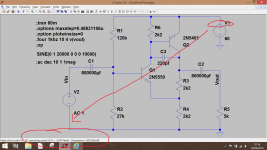
Hello ! very very much and finally .... look at the FFT 😀
I have set:
Stop time = 80ms
and in the FFT
Start time =40ms and End Time = 80ms
I told you that i am slow, very slow ... 😱
And the result is attached ! finally !!!! Thank you very much for your patience 🙂
Speaking of the circuit is impressive how there is only a little bit of 2nd order distortion ... is not amazing ?
I have also decreased the gain at almost 1 and the V1 = 30V
I should find some nice kit for this voltage ... the high voltages are much less common but 30V is common ... i could even use a +/-15V dual supply i guess
I think i will try the buffer.
Thank you very much indeed
Kind regards, gino 🙂
P.S. better to get a tattoo with these values 😀
You're welcome 🙂 Its good for me to do all this too because I'm certainly no expert on LT, in fact it was only through reading Bob Cordells book that I was able to find a way in and for it to start to make some sense.
Hello and i swear the last question ....
As i am thinking to use for V1 two 12V SLA batteries in series that when charged are around 13.5V for a total of V1= 27 V (already simulated and it is ok) how can i understand how much current the circuit will draw ? 🙄
I would not like to have to recharge them very often ... 🙁
Do you think that the idea is sane ?
or better a 30V PS kit ? and which one ?
Thanks a lot , gino
You can either add a low value resistor in series with the supply to read currents (and more conveniently measure AC ripple currents in power supplies) or if you just want to measure current consumption you can hover over the terminal of the PSU and read the current draw and power consumption of the circuit.
Attachments
I'm stuck at posts 56 & 57.
I get 73.xx% distortion when I look at the error log.
And the FFT starts at 1kHz.
same problem as Ginetto @ post57
by post63 solved !
How solved?
There were a few slightly different circuits posted so I'm not sure which version you are using but when you get massive thd like that then make sure the timestep setting is appropriate to the frequency and to length of time the FFT will run.
Getting there.
added back in the 220pF and now the 20kHz distortion is 0.018% (-74.6dB)
That sounds more reasonable
post65 working.
still getting 0.018% rather than 0.013%
Quite slow to get all 80ms into the simulation.
I'll pick up on post73 tomorrow.
Yes, long simulations (and 80ms is getting long for LT) can take quite a while. The one I did at the end of post #74 which was 800ms took around 2 to 3 minutes to complete.
You're welcome 🙂 Its good for me to do all this too because I'm certainly no expert on LT, in fact it was only through reading Bob Cordells book that I was able to find a way in and for it to start to make some sense.
Hello and thanks a lot again for your very kind and extremely valuable support
I hope the book is this one i bought 🙄

Let's hope to catch something ... but i am pessimistic
I had two very bad moments in my humble life
The first when i had to put glasses on ... was a drama. It changed my life.
But the very devastating moment was the second one ... when i realize that i do not understand math ...
For me math is behind the universe ... is the expression of God !
There is something of unexplicably right in math, something pure, something amazingly beautiful ...
And these sim SWs are just that ... applied mathematics
And i am truly fascinated by these programs ... like i was when watching Beutiful Mind
It is not trivial that the ability to do math is used to measure intelligence
To be honest i have to say that i was better at math when i was very young
Than the puberty came and distracted me a little ... from math i mean.
You can either add a low value resistor in series with the supply to read currents (and more conveniently measure AC ripple currents in power supplies) or if you just want to measure current consumption you can hover over the terminal of the PSU and read the current draw and power consumption of the circuit
Great ! You are very right ! i did not think about this
For low i guess you mean something like 100 ohm ? done !
Before committing myself to build something (i have already ordered some breadboards and a bunch of parts anyway) i would like to simulate some very textbooks circuits ... to increase my sensibility about the impact of changing values.
I have already modified the basic circuit just to do some practice with the commands and for basic tasks it seems quite straightforward
As i have noticed that almost no gain is necessary in many occasions with power amps i am more and more interested in unity gain buffer, always discrete of course
I have already taken part in some 3D on diamond buffers ... they like their symmetry for instance ... and their ability to drive everything with spectaculare low distortion i understand (now i can see for myself) 😉
There are some designers here whose comments i read with extreme interests
But sometimes i get confused
Without mentioning Him, he said that the nature is single ended in general
Not symmetrical i mean
And i was sold on this.
And then he designed a series of power amps based on a super-symmetry concept 😱😕 🙁
I have to state that i like very very much symmetry ... on a aestetic only basis of course 😀
But this is a very important assumption ... it sets the path to follow.
To end i am also looking for a LTSpice manual that explains more or the settings in depth, always in the hope to understand something
Thank you so much again
Have a nice day. Gino

... Yes, long simulations (and 80ms is getting long for LT) can take quite a while.
The one I did at the end of post #74 which was 800ms took around 2 to 3 minutes to complete
Hi and sorry but i have to ask you
I ended up using 40 ms 😱 i have no patience
What are the benefits to run long simulations ? 🙄
If necessary i can wait a little more
Thanks and regards, gino
thanks for continuing to think about why my searches don't show anything.Quite a posts since yesterday... and something I forgot to add. When searching for .asc files you probably should have the option to show "hidden files and folders" checked because LT lives in the program files and unless you instruct it otherwise it will save files there.
I am set up as administrator and I have show all files ticked all the time.
I am still not allowed to open folders that have a black arrow inside the icon.
That is the book 🙂 and it has a large section on simulation together with a link to files on Bobs web site that cover all the examples in the book.
Yep, maths is my big big failing too... and wearing glasses 😉 but its distance things I can't see, close up and I've got eyes like a microscope.
The beauty of LT is that its pretty perfect when adding things like low value resistors to monitor things. Try 0.1 or 0.01 ohm. That might be a problem with real instruments but not with LT. I just tried 0.000001 ohms and the "AC" current drawn from the supply and the DC values are just the same as using higher values.
Long runs, particularly on AC coupled circuits give more resolution on the FFT (the fine lines).
thanks for continuing to think about why my searches don't show anything.
I am set up as administrator and I have show all files ticked all the time.
I am still not allowed to open folders that have a black arrow inside the icon.
Its a puzzle !
I found this (you might need a Microsoft account to access although its an open and public forum) which specifically mentions the arrows along wit Firefox and Chrome.
Black arrows covering file folders! - Microsoft Community
Typing .asc in the search box should bring every single file on your PC up that has those file types. It should in W7 and it does in W8 (looks different but gives the same result).
Attachments
That is the book 🙂
Thanks a lot Mr. Mooly ! i will receive it soon i hope
You mean LTSpice files ? that would be great indeed !and it has a large section on simulation together with a link to files on Bobs web site that cover all the examples in the book
That is indeed what i was looking for actually. Thanks !
More or less the same here ... but also for close things there are lenses.Yep, maths is my big big failing too... and wearing glasses 😉 but its distance things I can't see, close up and I've got eyes like a microscope.
If i break my glasses i cannot drive ... for one thing.
The beauty of LT is that its pretty perfect when adding things like low value resistors to monitor things. Try 0.1 or 0.01 ohm. That might be a problem with real instruments but not with LT.
I just tried 0.000001 ohms and the "AC" current drawn from the supply and the DC values are just the same as using higher values.
Really a great SW indeed. I am sure i have only seen the tip of the iceberg
And it is already amazing. A good help also to understand circuits in general.
Long runs, particularly on AC coupled circuits give more resolution on the FFT (the fine lines)
Perfect ! i supposed so but now i have the confirmation
I will come again here in case i will find some other obstacles 😀
I am sure of this 😱
I hope you will be here at the time 🙄
Thanks a lot again and kindest regards, gino
You're welcome 🙂
Yes, LT is a brilliant piece of software and I've only scratched the surface myself... I need to learn more.
(I'll be a bit scarce around here tomorrow)
Yes, LT is a brilliant piece of software and I've only scratched the surface myself... I need to learn more.
(I'll be a bit scarce around here tomorrow)
Karl, you're doing an excellent job of guiding gino in, I'm impressed!
gino, here is a tutorial that I came across some time ago, which does it in a nice, hand holding way - Index of /LTSwitcherCAD/SwitcherCAD-Tutorial_English/pdf-File. There is also a User Group which has a huge amount of contributed material, if you're interested ...
gino, here is a tutorial that I came across some time ago, which does it in a nice, hand holding way - Index of /LTSwitcherCAD/SwitcherCAD-Tutorial_English/pdf-File. There is also a User Group which has a huge amount of contributed material, if you're interested ...
The majority carriers are different for PNP and NPN devices. This effects the semiconductor design but not the mechanical construction.
Because of the difference in majority carriers, the performance of the two is different with the PNP being more difficult to manufacture to mirror the NPN performance in high power devices.
This is also true for P and N type MOS FETs.
BJTs are actually minority carrier devices. FETs, by contrast, are true majority carrier devices.
Karl, you're doing an excellent job of guiding gino in, I'm impressed!
gino, here is a tutorial that I came across some time ago, which does it in a nice, hand holding way - Index of /LTSwitcherCAD/SwitcherCAD-Tutorial_English/pdf-File. There is also a User Group which has a huge amount of contributed material, if you're interested ...
Hi and thank you very much. I will read it soon.
I need time to digest even easy things.
After some practice i will look at that User Group.
My main interests are circuits usable for line stages and power supplies.
I think that the line preamp is a very important element of a chain, unless we use an integrated of course.
But the nice thing with the preamp is that it allows to choose from different power amps with different power.
Thanks again and kind regards, gino
Karl, you're doing an excellent job of guiding gino in, I'm impressed!
gino, here is a tutorial that I came across some time ago, which does it in a nice, hand holding way - Index of /LTSwitcherCAD/SwitcherCAD-Tutorial_English/pdf-File. There is also a User Group which has a huge amount of contributed material, if you're interested ...
Thanks Frank. Great link for ginetto.
I'll not be around for a few hours now... have fun 😀
Thanks a lot Mr. Mooly ! i will receive it soon i hope
You mean LTSpice files ? that would be great indeed !
That is indeed what i was looking for actually. Thanks !
You're welcome 🙂
Yep, without Bobs book I would still be staring at a grey screen and wondering what its all about. It will all start to make more sense when you read it.
A large part is devoted to simulation and crucially, it tells you exactly what to do key by key almost... no knowledge is assumed... which is where most texts fail.
You will be impressed by what LT really can do... far far more than we have covered with your preamp.
- Status
- Not open for further replies.
- Home
- Member Areas
- The Lounge
- NPN versus PNP