I think the clk should be going to ground. Do you have another IC that you could install?
Since this is not a common amp, if no one else steps in to help, it would help me greatly if you would include the PDF page number and the map reference for the general area of the various components.
Since this is not a common amp, if no one else steps in to help, it would help me greatly if you would include the PDF page number and the map reference for the general area of the various components.
Yes I have one more spare 3825, and also the original piece still. I’ll try another brand new one.
Generally I’m between pages 50-54 in the sm. I know it’s a bunch of jumping around in this thread though. I’ll try to guide a little better.
[mention]miniman82 [/mention] - can you post a photo of what you have on pin 4 of the uc3825 if you can still get to it? Set scope to dc, 1vDiv please. Presuming your 6000 powers up.
Last edited:
In an interesting update, I received a call today from one of Crown's designers for this amp, who helped me walk through a few things to check!
Since my amp is not powering down (Nor powering up without D20 with 2x 1n4148s) under situations where it should be powering up/down correctly, he's thinking U1 has failed. I'll be replacing U1. U1 is supposed to drive the UC3825 LOW to power the PS on, and HIGH to power the PS off.
He also mentioned that most of the PCBs in this amp are 4-layer, and only the smaller boards like the input, status, and output boards are 2-layer.
And one more mention since I've been having ILIM issues, is suggested I check the connections at U11 to X28 and X30 (Not on the schematic, but essentially these are + and - busbar) as these opAmps or their connections to the busbar may cause startup issues as well.
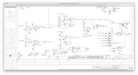
I've attached schematic of U1 (Which has DIS) and the main PS driver (Which also has DIS, and D20 shown).
Since my amp is not powering down (Nor powering up without D20 with 2x 1n4148s) under situations where it should be powering up/down correctly, he's thinking U1 has failed. I'll be replacing U1. U1 is supposed to drive the UC3825 LOW to power the PS on, and HIGH to power the PS off.
He also mentioned that most of the PCBs in this amp are 4-layer, and only the smaller boards like the input, status, and output boards are 2-layer.
And one more mention since I've been having ILIM issues, is suggested I check the connections at U11 to X28 and X30 (Not on the schematic, but essentially these are + and - busbar) as these opAmps or their connections to the busbar may cause startup issues as well.
I've attached schematic of U1 (Which has DIS) and the main PS driver (Which also has DIS, and D20 shown).
Attachments
From Crown:
Hello,
I studied the schematic to be able to answer the questions that you have. It has been a while.
The power supply does not have a input into the crowbar circuit, that signal (crowbar drive) comes from the amp section. The output from the crowbar circuit (signal crowbar) shuts off the power supply through U3 pin 11. The power supply does have several criteria to keep it from running :
Over voltage, Under voltage, over current, over temperature, and low voltage power supply output not in acceptable range. They are found at U1, inputs to pin 10, output is pin 13. This output goes to the UC3825 and the HIP4081, this is the disable signal. To run, it is kept low. I would look here to find if the signal is right.
You can run the power supply with the 6 pin disconnected from the amp. DO NOT plug it back into thew amp section until the secondary caps are discharged.
The amp will draw current from the power supply at idle, if it is 5A, i suspect the output stage is sleeping. There are several inputs to keep it from going active, on the amp board, U46 looks at low voltage power supplies (LP OK), low energy (from the power supply), and PROP. VCC (Proportional VCC) must be in the right range also, U45, pin 2 and 14. LP OK and VCC OK will prevent the output stage from going active if they are not right. The amplifier goes into fault condition if the output of the amp goes into DC. DC protect will fire off the crowbar circuit.
I would look at C57 on the amplifier board, if it leaks, it will not start.
If you have any more questions, feel free to ask.
Dan
Also, Dan mentioned that this is not a Class-D amp. Its a Class-I. He also said it was a 'monster'. Interesting.
Still looking at the schematics from post #43, I was able to set up the PS to be operational by replacing R118 (4.7k) with a 220R resistor. This allowed other components such as U1 and U3 to pull HARDER down on the DIS pin of the HIP4081.
Now the power supply seems operational, and under ILIM, Lo, and Hi input voltage tests it does properly shut down, and also turn back on when back within operational ranges.
SO, I'm not sure if R118 can honestly stay situated with a 220R, but for now I'm going to work with it. D20 is back to just a single 1n4148.
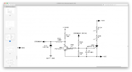
Next, I realized why the amp was actually self-crowbar'ing. Call it a rookie mistake but I was using a PNP transistor instead of an NPN in Q52. I originally FRIED the PZTA42T1 probably because I modified D20, and I had replaced it with an s2a1220 which was not right at all. I instead used an MJE340 because it has a much better rating for this application. Crowbar schematic attached.
Crowbar circuit is in, and the PS is able to power up fairly smooth. It draws a LOT of current but settles at about 4A.
Now the power supply seems operational, and under ILIM, Lo, and Hi input voltage tests it does properly shut down, and also turn back on when back within operational ranges.
SO, I'm not sure if R118 can honestly stay situated with a 220R, but for now I'm going to work with it. D20 is back to just a single 1n4148.
Next, I realized why the amp was actually self-crowbar'ing. Call it a rookie mistake but I was using a PNP transistor instead of an NPN in Q52. I originally FRIED the PZTA42T1 probably because I modified D20, and I had replaced it with an s2a1220 which was not right at all. I instead used an MJE340 because it has a much better rating for this application. Crowbar schematic attached.
Crowbar circuit is in, and the PS is able to power up fairly smooth. It draws a LOT of current but settles at about 4A.
Attachments
Last edited:
AAAAANDDDDDD.... I cannot believe this. The amp seems to now be able to FULLY power up! Its drawing 12A idle and there is barely ANY DC on the outputs. So, the outputs are now going LIVE! Guess its time for audio testing.
Honestly I cannot even check it. The circuit is overly sensitive and when I touch anything to the related pins the ps flips into protect unfortunately.
No need to re-check but in many cases, using the probe in 10x will reduce the load on the circuit and allow testing.
Crown responded to me again, and said R118 at 220 ohms is likely OK.
He also said for me to comb through section 4.7 of the SM, to adjust for over/under-lapped.
He also said for me to comb through section 4.7 of the SM, to adjust for over/under-lapped.
The next item is to adjust or at least check is overlap / under lap on the amp section. The adjustment is in section 4.7 in the service manual. What you are looking for is a square corner on the waveform, under lapped is very obvious, overlapped is not. To make sure is is not overlapped, turn the pot until it is under-lapped, and then gently rotate it until the under lap is gone. You are done turning the pot when the movement in the wave form stops, and further is over-lapped. Get to the point where the movement just stops. If you have to turn the pot a lot all of a sudden in it's travel to get any change in the waveform, most likely overlapping is occurring. Look at your current draw. Being overlapped causes waste energy in the output stage, stresses it, and will lead to a early demise. With the current draw where it is, 11.5A, you are really close, just make sure 1 channel is not under-lapped, and the other over-lapped.
I ran through 4.7 in the SM.
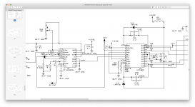
One more thing back on the PS. The disablement circuit as shown here. With modifying R118 to a 220ohm, the amp does power on and off accordingly, but the voltage is right on the edge of 1.7vDC on DIS pin of the HIP4081. Breath on it and it goes one way or another, which is why I could not test this voltage very well with scope or meter. Too much on the fence for reliability.
So, I fixed a 10ohm resistor after D20. This allows the voltage to drop further by the protection circuitry (to 1.3v) and allows the amplifier to stay running more reliably; while still providing ample space for protection circuitry to engage (~3vDC on DIS under protect enabled).
Attachments

Come to think, I'm honestly not even sure why this amp is connecting CLK to DIS. I wonder if just plain old removing D20 all together would be the viable? The protection circuitry floats LOW for enable, and HIGH for disable, and should make the PS turn on/off directly without a connection back to CLK...
I'm not sure why DIS needs to see CLK at all. Especially since CLK provides a low duty square wave - I'd think the narrow high points of the square wave might try and trigger the HIP4081 to cycle on/off at the frequency of CLK. Perry do you follow or know?
I'm not sure why DIS needs to see CLK at all. Especially since CLK provides a low duty square wave - I'd think the narrow high points of the square wave might try and trigger the HIP4081 to cycle on/off at the frequency of CLK. Perry do you follow or know?
Last edited:
If it's used as a blanking pulse, it could be providing some deadtime in the drive.
Crown will know definitively.
Crown will know definitively.
well i know this i think the post might of just saved my ***. Dr zeus do u have a copy of the service doc.s for this big girl?"
I have one of theses in my show and i'm trying do work out stuff with mine here. any link or pdf files would be welcome..
I have one of theses in my show and i'm trying do work out stuff with mine here. any link or pdf files would be welcome..
Come to think, I'm honestly not even sure why this amp is connecting CLK to DIS. I wonder if just plain old removing D20 all together would be the viable? The protection circuitry floats LOW for enable, and HIGH for disable, and should make the PS turn on/off directly without a connection back to CLK...
I'm not sure why DIS needs to see CLK at all. Especially since CLK provides a low duty square wave - I'd think the narrow high points of the square wave might try and trigger the HIP4081 to cycle on/off at the frequency of CLK. Perry do you follow or know?
Is there any chance u still have the link to or a copy off the service doc's for the crown?
Pls check you messages. Desperate for a part fir thisMy JBL contact was not able to source a schematic for the 6000GTI, the same contact provided me with the service manual. They said that the schematics could not be found by their internal teams (So, they tried). They are now trying again for the A3000GTI schematics.
I'm combing through, and definitely the following components off the board have failed.
Q52 - R33 marking
Q53 - MCR72-8 - Dead shorted
Q56 - 1AM Shorted across all 3 legs 20~90ohms. Replaced already
R26 - C840 (Blew chunks)
R35 - 1k - Blew open. Replaced already
R134 - C840 (Might be OK actually)
D13 - ? - Blew open
Can someone help me figure out and suggest what D13 would be? There are no markings on the glass of this diode other than a black band. 4148?
- Home
- General Interest
- Car Audio
- Not another JBL Crown A6000GTI thread