Photo
Also for anyone working on one of these, please note that REMOTE may need to be applied AFTER +- else the amp may go straight into protect if all power is switched on at once.
Also this sucker hums pretty loudly. Insane
Also for anyone working on one of these, please note that REMOTE may need to be applied AFTER +- else the amp may go straight into protect if all power is switched on at once.
Also this sucker hums pretty loudly. Insane
Attachments
Last edited:
Well now I'm going backwards. I hooked up the audio side and the amp fell into protect again, and now I cant get the PS to power by itself. Something different on the PS board has failed.
Now the amp is throwing LVPS NEG(E5) and ILIM with the audio boards disconnected.
Now the amp is throwing LVPS NEG(E5) and ILIM with the audio boards disconnected.
Last edited:
Backward and forwards. The PS by itself is only powering on correctly about 10% of the time. Mostly it signifies ILIM or LVPS Negative problem.
Page #28 of the SM
LVPS NEG(E5) Low voltage power supply negative no good
ILIM (E2) Power supply over current or audio section fault
Sometimes when it does power up, the Battery OV light shows very dimly, but the OV/UV thats over/under voltage circuit works when I change my external PS to 16v or 10v.
Battery OV (E1) Voltage greater then 16V
Battery UV (E6) Voltage less then 10V
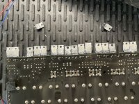
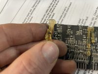
On the Audio board, I actually did find a manufacturing fault. All 8x rectifiers (R3060P2 devices) were poorly soldered, and 2 of them only had 1 leg soldered each. (Photos)
These rects being poorly soldered are likely to have caused this amp to crowbar and then mess things up on the PS side of things.
Mainly, I'm getting ILIM. Seems there is an 8-pin opamp at U11 near the power terminals which actually helps to control the ILIM circuit. Also an LM339 but I replaced all those in the amplifier already.
Page #28 of the SM
LVPS NEG(E5) Low voltage power supply negative no good
ILIM (E2) Power supply over current or audio section fault
Sometimes when it does power up, the Battery OV light shows very dimly, but the OV/UV thats over/under voltage circuit works when I change my external PS to 16v or 10v.
Battery OV (E1) Voltage greater then 16V
Battery UV (E6) Voltage less then 10V
On the Audio board, I actually did find a manufacturing fault. All 8x rectifiers (R3060P2 devices) were poorly soldered, and 2 of them only had 1 leg soldered each. (Photos)
These rects being poorly soldered are likely to have caused this amp to crowbar and then mess things up on the PS side of things.
Mainly, I'm getting ILIM. Seems there is an 8-pin opamp at U11 near the power terminals which actually helps to control the ILIM circuit. Also an LM339 but I replaced all those in the amplifier already.
Photos
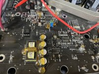
Also the glue is a royal working on this amp. Pulled off an smd transistor on disassembly on accident.
Also the glue is a royal working on this amp. Pulled off an smd transistor on disassembly on accident.
Attachments
-
 52DCE871-7CD9-4238-A0C4-6549B5A35B38.jpeg396.4 KB · Views: 155
 -
 E4A6F2E6-61D8-4B39-A99C-EF28C7B6A931.jpeg276.4 KB · Views: 155
 -
 171ED9AC-42CC-4044-9A79-232A469A15A3.jpeg306.6 KB · Views: 169
 -
 A9CED514-ABA0-4A19-BBC6-F6BE0D460B85.jpeg130.8 KB · Views: 158
 -
 C88C17C9-38A8-4BB9-9758-5A4503CEC819.jpeg350.4 KB · Views: 143
Back on this amp. Before getting the FULL SM, I decided it would probably be best to replaced ALL Uxx ICs in the PS since many of them had failed and I was circling round and round.
Long and short of it, I replaced everything EXCEPT the U2 HIP4081AIB. Probably a mistake to skip this one, but its a bit harder to find and costs a bit more.
The amp no longer has any status problem/LEDs, BUT it also will not power up correctly fully
The "Pre" power supply is working. I'm getting +-24v out of the Pre-PS, +-15v, and +5v out of the other regulation components as well.
The amp is drawing 2A from the bench, and everything seems 'normal' as-in ready to 'go', but the main power supply is not booting up.
Main PS is driven by the U2; HIP4081.
1: 14.18
2: 0.001
3: 2.123
4: 0
5: 2.440
6: 2.443
7: 14.86
8: 5.35
9: 5.35
10: 14.19
11: 11.96
12: 11.96
13: 0.007
14: 0.007
15: 0
16: 0
17: 0.006
18: 0.006
19: 11.96
20: 11.96
Anything jump out here? I'll be researching these readings over the weekend.
Thank you
I wouldn’t say driven, more like steered. That IC drives all the the PS FET gates, but it gets its marching orders from the UC3825. Are you getting drive waves out of the 3825?
Correction:
Main PS is driven by the U2; HIP4081.
1: 14.18
2: 14.86 <--
3: 2.123
4: 0
5: 2.440
6: 2.443
7: 14.86
8: 5.35
9: 5.35
10: 14.19
11: 11.96
12: 11.96
13: 0.007
14: 0.007
15: 0
16: 0
17: 0.006
18: 0.006
19: 11.96
20: 11.96
Pin 3 has a square wave that rests at 2v, and a low duty cycle up to 4v. Looks clean
Pin 5 & 6 have a nice, clean; 0-5v square wave
Pin 8 & 9 are at 5v, with 'noise'. Makes a rather thick line on the scope. This seems irregular.
Last edited:
I removed D20 as I was going to test the output of U4 ping 4 and to my surprise the amp TRIED to power up. It was VERY BRIEFLY trying to draw about 15A and so I pulled the power super quick. I do not know if it would have FULLY powered up. I then replaced D20 with a new 1N4148, and amp is back to not powering up as it was in post #27.
Hmmm...
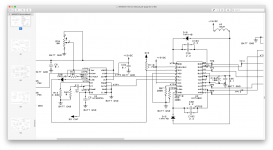
Heres the schematic I'm looking at.
Hmmm...
Heres the schematic I'm looking at.
Attachments
Last edited:
I wouldn’t say driven, more like steered. That IC drives all the the PS FET gates, but it gets its marching orders from the UC3825. Are you getting drive waves out of the 3825?
Yes, HIP4081 pins 5 & 6 are being driven by pins 11 and 14 of the UC3825A. Clean square wave as mentioned.
U4 - UC3825
1: 0.014
2: 2.575
3: 4.85
4: 2.686 (Narrow square wave)
5: 2.983
6: 2.047 (Saw/triangular wave)
7: 2.046 (Saw/triangular wave)
8: 5.61
9: 0.013
10: 0.013
11: 2.433 (5v clean square wave)
12: 0.013
13: 5.14
14: 2.432 (5v clean square wave)
15: 14.86
16: 5.14
1: 0.014
2: 2.575
3: 4.85
4: 2.686 (Narrow square wave)
5: 2.983
6: 2.047 (Saw/triangular wave)
7: 2.046 (Saw/triangular wave)
8: 5.61
9: 0.013
10: 0.013
11: 2.433 (5v clean square wave)
12: 0.013
13: 5.14
14: 2.432 (5v clean square wave)
15: 14.86
16: 5.14
U4 pin 4 and U2 pin 3 connect back to what's labeled as DIS after a 4.7k on the above schematic. Board trace shows this connecting through multiple components, including U1 and U3, both LM339.
U3 pin 5 is also connected to SS CAP on U4 (UC3825A)
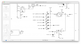
Schematic:
U3 pin 5 is also connected to SS CAP on U4 (UC3825A)
Schematic:
Attachments
TP3 has 0.092v.
To check something, I went ahead and removed R118.
TP3 then had 0.063v.
My thought was removing R118 would then REMOVE all outside disablement components from the HIP4081 and UC3825, and I thought the amp would possible try to power up. It unfortunately did not.
So, the only way this amp even 'tries' to power up is when I have D20 removed. Removing D20 disconnects the oscillator/clock between the UC3825A-LEB and the HIP4081-DIS.
I think the HIP4081 is partially failed. For whatever reason it may not be working with LEB/clock connected to DIS (Pin 3).
Anybody follow at all?
HIP4081 pin3 (DIS) from what I understand shuts the chip down when DIS is over 1.7v threshold. I'm getting 2.123v on it.
Could my new SG3825A be floating too high? As mentioned, scope is showing a square wave with a floor voltage of 2v, and a low duty cycle square wave up to 4v on pin 4 (LEB) hence 2.123v on the dvm.
If I put a second 1n4148 in series with D20, possible get the voltage dropped enough for the amp to boot. Thoughts?
Last edited:
Its 2am and I'm going to stop for now.
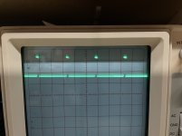
I put a SECOND 1n4148 diode in series with D20, AND THE PS BOOTED UP! ~320v rail. Whines like bumble-bee buzzing around your face.
Now, I have a very dimly lit ILIM. Possible from the audio side, though I did not yet connect the rail voltage connector so that could be why.
I put a SECOND 1n4148 diode in series with D20, AND THE PS BOOTED UP! ~320v rail. Whines like bumble-bee buzzing around your face.
Now, I have a very dimly lit ILIM. Possible from the audio side, though I did not yet connect the rail voltage connector so that could be why.
The waveform is exactly the same with two 1n4148s at D20 tied serially. The second 4148 essentially just lowered the over-all voltage by about 0.4v, which as I understand is a go/no-go voltage for the HIP4081 at 1.7v. So, essentially the second diode tricked the PS into booting up. It is extremely close and seems like it might want to shut down still; I feel a 3rd diode would improve it further.
1v/Div @ 0.2ms
1v/Div @ 0.2ms
Attachments
Last edited:
I didn't put a 3rd D20 diode in. Hooked up the RAIL plug to the amp side. Amp powered on with about 5 amps of draw at idle; after pulling about 20A for about ~3 seconds. Seems like idle draw is lower than spec. Then R117 started to smoke in the crowbar circuit, shorting out Q52. Removed both.
Powered the amp on again, and I found some DC on speaker terminals.
CH1: <0.050vDC
CH2: 0.5vdc
I *think* theres a voltage offset adjustment in the SM. Looking for it. I do not know if there is audio coming out - yet.
I replaced R117, and am going to install a temporary 2SA1220A into Q52.
Powered the amp on again, and I found some DC on speaker terminals.
CH1: <0.050vDC
CH2: 0.5vdc
I *think* theres a voltage offset adjustment in the SM. Looking for it. I do not know if there is audio coming out - yet.
I replaced R117, and am going to install a temporary 2SA1220A into Q52.
Last edited:
No audio on either channel. R215 CH2 DC offset has no effect.
I need to trace back through all Crowbar circuits to see where the hit is coming from.
I need to trace back through all Crowbar circuits to see where the hit is coming from.
Crowbar activation is not coming from audio board as Q40 doesn't have much pushing crowbar on. Q40 Collector is connected to the Crowbar drive, which sees -rail through R33 & R35.
Q40 - MMBTA92L:
1: 0vDC (base)
2: -4.06vDC (Emitter)
3: -160vDC (Collector)
For testing, I re-installed ALL crowbar parts including Q52 and Q53 (I didn't have Q53 installed ALL THIS TIME).
The PS crowbars. Doesn't matter if the audio board is connector or not. The parts I install get instantly hot.
Crowbar is run out of U3, LM339 pin 11, which has 14.7vDC on it which I am not totally sure why that is exactly.
Maybe U3 is bad seeing as U3 is also controlling DIS of the HIP4081.
- Home
- General Interest
- Car Audio
- Not another JBL Crown A6000GTI thread