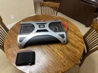
Ahh, sigh... I seem to attract these pesky little amps. Second one in about a month across my shop, 4th one ever. Good news is, this one is mine. ALL MINE!
No clue where to start. Its all here just need to find a way to start taking it apart. Something is loose inside, and then figure out what is what. Nothing looks burned at all. Last owner owned it for 15 years from new, said he spent $6k on it new.
I'm supposed to be getting a schematic for it. Hopeful. Doubtful. Waiting.
Last edited:
If you need any test point voltages or waveforms let me know, I should have all the hardware replaced and boards solidly mounted to the chassis in the next couple weeks. I’m not expecting any issues with it, but 2 amps for troubleshooting purposes is better than one. And if you do get a schematic, be sure and share it so I have it for my files as well.
I may be on to something with mine. It attempts to power-up as is, but only draws 3A of current at idle, though when I hit the REM switch it does draw 150A surge.
I'm not getting ANY signal to the FET gates, IRF1405 and there are 48 of them.
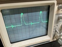
The PS is using an SG3525 which at this point actually seems to be alright, so I'll be looking at the PS drivers next as theres nothing beyond the SG. The waveform on pins 11/14 are as pictured with my scope set to 5vDiv DC.
SG3525AP
1: 5.22
2: 5.22
3: 0.025
4: 0.336
5: 2.090
6: 3.560
7: 2.090
8: 0
9: 1.514
10: 0.069
11: 1.692
12: 0
13: 13.7
14: 1.665
15: 14.29
16: 5.22
I'm not getting ANY signal to the FET gates, IRF1405 and there are 48 of them.
The PS is using an SG3525 which at this point actually seems to be alright, so I'll be looking at the PS drivers next as theres nothing beyond the SG. The waveform on pins 11/14 are as pictured with my scope set to 5vDiv DC.
SG3525AP
1: 5.22
2: 5.22
3: 0.025
4: 0.336
5: 2.090
6: 3.560
7: 2.090
8: 0
9: 1.514
10: 0.069
11: 1.692
12: 0
13: 13.7
14: 1.665
15: 14.29
16: 5.22
Last edited:
Found a few faults in the PS.
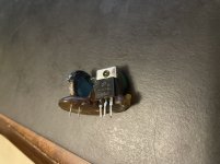
Q53: OnSemi MCR72-8 https://datasheet.octopart.com/MCR72-8G-ON-Semiconductor-datasheet-524805.pdf
R134: C840 ceramic thermister C 840, TDK PTC thermistors for overcurrent protection, pitch 5,08mm, B599 and B598 series - elpro Elektronik
Other possibly shorted devices
Q56: 1A SMD
D13: ?
Q53: OnSemi MCR72-8 https://datasheet.octopart.com/MCR72-8G-ON-Semiconductor-datasheet-524805.pdf
R134: C840 ceramic thermister C 840, TDK PTC thermistors for overcurrent protection, pitch 5,08mm, B599 and B598 series - elpro Elektronik
Other possibly shorted devices
Q56: 1A SMD
D13: ?
Its not my scope. I was grounded to one of the busbars. That drive signal is rough. Its also not getting past the drivers.
Also are you finding that about every 2~4 FETs they may be connected source to drain from one to the next FET?
Also are you finding that about every 2~4 FETs they may be connected source to drain from one to the next FET?
Does the negative bussbar have solid continuity to the ground pin of the 3525? If not you can’t reference the bussbar as a ground, but if it does then you were in fact grounded correctly and that wave has a butt ton of ringing in it.
This isn't a standard switching power supply. If I'm not mistaken, it's an H-bridge operating at about 800Hz. Someone stated (don't know if it's true) that this supply uses an iron core of some type and not a ferrite core.
The negative busbar does have good connectivity to pin 12 of the SG3525.
I'm finding for every-other bank, FETs are connected from drain of one bank to the sources of the next bank and alternates as I test around the transformer. I wasn't expecting that.
I'm finding for every-other bank, FETs are connected from drain of one bank to the sources of the next bank and alternates as I test around the transformer. I wasn't expecting that.
Last edited:
Yes, it’s H-bridge just like the JL 1000/1. No one can know for certain what the core is made of unless they’ve disassembled it, but based on the low frequency I would not expect ferrite. The sound it makes actually reminds me of the 400hz power converters on board Navy ships, just not as loud.
Last edited:
Ive received all service manuals for JBL Crown A6000GTI! There are 9 documents in all. Let me know if you need a copy.
Perry, check your yahoo inbox.
Perry, check your yahoo inbox.
Reading through section 3.3.3. is interesting. The SG3525AP is only being used with 2xIRF540N for the low voltage 24v supply. The large main supply is turned on later down line.
I'm trying to get the actual schematics as well since they are not in the SM documents.
Also section 3.3.2 is likely a case for me.
On my amp, my MCR72-8 SCR dead shorted across all 3 legs. Also the C840 PTC next to it blew partially apart. Another C840 also nearby. All three pieces glued together.
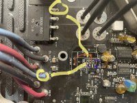
I'm finding possible faults with Q56(1A). D13, and Q52(R33) where it would appear these devices may also have shorts. Q56 between 1-3, D13, and Q52.
Photo next
I'm trying to get the actual schematics as well since they are not in the SM documents.
Also section 3.3.2 is likely a case for me.
On my amp, my MCR72-8 SCR dead shorted across all 3 legs. Also the C840 PTC next to it blew partially apart. Another C840 also nearby. All three pieces glued together.
I'm finding possible faults with Q56(1A). D13, and Q52(R33) where it would appear these devices may also have shorts. Q56 between 1-3, D13, and Q52.
Photo next
Last edited:
My JBL contact was not able to source a schematic for the 6000GTI, the same contact provided me with the service manual. They said that the schematics could not be found by their internal teams (So, they tried). They are now trying again for the A3000GTI schematics.
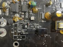
I'm combing through, and definitely the following components off the board have failed.
Q52 - R33 marking
Q53 - MCR72-8 - Dead shorted
Q56 - 1AM Shorted across all 3 legs 20~90ohms. Replaced already
R26 - C840 (Blew chunks)
R35 - 1k - Blew open. Replaced already
R134 - C840 (Might be OK actually)
D13 - ? - Blew open
Can someone help me figure out and suggest what D13 would be? There are no markings on the glass of this diode other than a black band. 4148?
Last edited:
Tracing back since the pads of D13 were measuring 40ohms, I found U3 - LM339D short 40ohms across pins 11-12. Replaced.
Amp still not powering up. I'm actually thinking since Q52 - R33 is removed because it is shorted; is still not allowing the PS to power up.
Amp still not powering up. I'm actually thinking since Q52 - R33 is removed because it is shorted; is still not allowing the PS to power up.
- Home
- General Interest
- Car Audio
- Not another JBL Crown A6000GTI thread