So what isn't? I thought about trying a Zen I/V also, which has the advantage of using the same transformer as the D1, I think, and I have a small stash of 2SK170 and 2SJ74. Maybe the SEN, CEN that EUVL developed. (Is there a BEN? 🤣)
I'm game for trying pretty much any I/V that can be connected with a TDA1541A. I'm open to suggestions, but don't want to take peppennino's thread to far OT.
I'm game for trying pretty much any I/V that can be connected with a TDA1541A. I'm open to suggestions, but don't want to take peppennino's thread to far OT.
Try Pedja Rogic IV.So what isn't? I thought about trying a Zen I/V also, which has the advantage of using the same transformer as the D1, I think, and I have a small stash of 2SK170 and 2SJ74. Maybe the SEN, CEN that EUVL developed. (Is there a BEN? 🤣)
I'm game for trying pretty much any I/V that can be connected with a TDA1541A. I'm open to suggestions, but don't want to take peppennino's thread to far OT.
Very nice too. I had D1 (without the buffer transistors though), I swapped recently for the above mentioned diamond buffer in an old CD player with a TDA1541. I made it because I had some nicely matched transistors - leftovers from a headphone amp project. Can't tell you which one sounds better. Both are great and fun to build.
I should probably try Zen/Sen/Cen IV.
The Pedja Rogic IV looks interesting; thanks for the suggestion. I have to say that the D1 sounds really good so far, so I think I may stick with it for a while. It'll give me time to see whether I have enough BC547/557, and which other IVs I want to try.
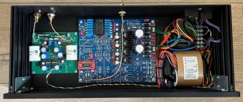
Here is my TDA1541A DAC with D1 I/V in a recycled chassis:
https://qwertyl1.wixsite.com/diyaudio/nos-tda1541-dac
https://qwertyl1.wixsite.com/diyaudio/nos-tda1541-dac
Attachments

Hello All - quick question regarding distortion on a TDA1541A with a tube output stage - what would be a reasonable distortion number - Best I could do after numerous tweaks is 0.03% / -70db - 1kHz 0DB with a 30kHz low pass filter.
Warm regards, Emil
Warm regards, Emil
Here’s a good article discussing R I/V values. He doesn’t discuss distortion numbers but does show spectral content and SNR vs I/V values.
Good stuff!
https://www.mvaudiolabs.com/digital/tda1541-iv-resistor-selection/
Good stuff!
https://www.mvaudiolabs.com/digital/tda1541-iv-resistor-selection/
Just an advise:
IN-L and IN-R are connected to a resistor to -Vb, while on the top it is on a source.That source depends on a time-lag (capacitor C1/C12), so the coductance will vary suring ‘warm-up’.
I had that myself.
Lost a TDA1541 that way. Add a pair of diodes with Vthreshold around 0,4 volt; otherwise the DAC output might (will) go awry that is Due North.
I had a similar problem on a PCM1704 by the way. I am subborn and stupid.
Thank you so much ggetzoff - To remove the guessing I build another board with a basic NE5532 output and with this I can get up to -87dB which is close to the datasheet - will work on this now till I can get to desired numbers and then just swop with the tube stage I have ready 🙂
![IMG_0588[236].jpg](https://www.diyaudio.com/community/attachments/img_0588-236-jpg.1178408/ "IMG_0588[236].jpg")
Hi, sorry for waking up this "old" thread but I'm in the mood for a new project and since having a few old 1541´s at hand, I think it would be fun trying out something like this. Now my problem is I'm really out of touch with computer stuff these days and don't manage to put the D1 Gerber files together to something the pcb makers accept. I have downloaded gerbview but so far only been able to open the file named "D1.gbs"
Probably relevant and definitely part of my problem is I only have access to Mac and growing up with windows, I'm not very familiar with the MacOs. So if there's a patient soul reading this and wants to help me figure it out, I would be very happy 🙂
Probably relevant and definitely part of my problem is I only have access to Mac and growing up with windows, I'm not very familiar with the MacOs. So if there's a patient soul reading this and wants to help me figure it out, I would be very happy 🙂
I believe I have a spare D3 board and I wrote a guide to populate it. Do you have experience with very small SMD soldering?
Golyd,
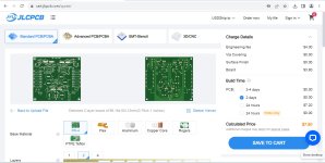
The zipped D1 Gerber file (https://www.diyaudio.com/community/...0400a-who-have-heard-both.347298/post-6872371) can be sent directly to a PCB manufacturer.
I tried it at the JLCPCB website and the zip file was recognized and opened:
The zipped D1 Gerber file (https://www.diyaudio.com/community/...0400a-who-have-heard-both.347298/post-6872371) can be sent directly to a PCB manufacturer.
I tried it at the JLCPCB website and the zip file was recognized and opened:
Attachments
Try Pedja Rogic IV.
Very nice too. I had D1 (without the buffer transistors though), I swapped recently for the above mentioned diamond buffer in an old CD player with a TDA1541. I made it because I had some nicely matched transistors - leftovers from a headphone amp project. Can't tell you which one sounds better. Both are great and fun to build.
I should probably try Zen/Sen/Cen IV.
Hello, I just build Pedja's discrete IV stage. I noticed that it's very temperature sensitive. The "upgraded" version used in the Aya 5 from Pedja is currently being simulated. For now, no reason why this should be more temperature stable.
Have you noticed same sensitivity?
if this was for me: thats a board for the tda1541 chip itself, right? might be interested, though no experience with smd soldering yetI believe I have a spare D3 board and I wrote a guide to populate it. Do you have experience with very small SMD soldering?
Yes, output offset measured below 2mV as well. Putting your fingers on the SOT23 transistors has big impact. Seems important to create somehow a stable temperature around those very low mass devices. I already made large collector PCB pads (3*6mm double sided with vias).Hi,
I do not recall that to be honest. Were you transistors matched?
I just come across this thread. I would like to share my work on a similar setup. I built a I/V conversion circuit based on D1 with 4 TDA1543 in parallel. I had used this for a very long time until 2021 when I bought a small Chinese DAC (SMSL Sanskrit 10th Mk2 using a AK4493 chip). The sound of this AK4493 DAC is very transparent compared to the TDA1543 + D1 but it is a bit too sharp. Recently I start to think about making some small changes to the old TDA1543+D1 DAC and reuse it as my primary DAC. In doing more research I saw this thread.
I attach here the circuit I previously built. I added a CCS to bias the IRF610 and did not use an output follower. 4 TDA1543 will give almost 10mA full swing current. I reduce the load resistance to 500 Ohms (3x1.5k to try to smooth out the tolerances among the resistors) and run the IRF610 real hot at 30mA idle. The voltage compliance of TDA1543 is 1.8V to Vcc-1.2V. I happened to run it at 5.6V approx and I picked 3.1V (about the mid point) as the voltage level at the input (source of IRF610). This is achieved by adjusting the pot at the gate. I left pin 7 (Vref for bias current setting) open.
Currently I am thinking of the following:
reduce the idle current to 20mA to reduce the heat load.
attach a resistor to pin 7 to add a bias current to the TDA1543s to see if this will bring any impact to the sound.
Attachments

My own experience with TDA1543 showed that pin7 is best left open i.e. the internal bias current generator should be switched off. Note in your schematic the +30V supply does need to be extremely low noise as terminating the I/V resistor to it gives zero PSRR. The original D1 was balanced (as far as I can recall) so relied on the CMRR of the next stage to eliminate PSU noise.
I can't find much info on this bias current of TDA1543, but believe that it exists for some reasons. Reading the spec the max bias current is 5mA, shared by both channels. Each channel gets 2.5mA, which is just enough to ensure that the full scale swing current is covered. This triggers me to think in the context of a Class A amplifier. It seems that the bias current will ensure that the DAC never "switch off", which might avoid some issues? Of course a DAC is essentially a current switch and switching is the norm. I still do not understand this.
- Home
- Amplifiers
- Pass Labs
- NOS TDA1541 + D1 I/V & output stage