FLAC and WAV are identical, quality wise.
It would be like saying a wav file sounded different after it was zipped and unzipped. It's lossless.
Or to put it differently, it would be like saying music played from a Seagate drive sounded different than music played from a Western Digital.
I use FLAC for lossless and OPUS for lossy. Both are FOSS. OPUS is by far the best lossy CODEC I've ever used. Opus (audio format - Wikipedia)
Last edited:
To be honest I haven't done any careful side by side comparisons but nothing stands out in casual listening. One theory is that flac files require more computer horsepower so the CPU works harder and generates more noise than it would playing a wav file. Like all else it's probably very system dependent.
I have three sever/streamers in my house. I get a real kick out of the super-inexpensive Raspberry Pi based one in my workshop. It drives a Tubelab SPP (Tubelab forum on this site) using old Heathkit iron into a set of Triangle Borea BR02s. Hours of pleasure while puttering about. The iPeng app I use to run it from an iPad is reasonably slick. A buddy controls his Pi using the Orange Squeeze app on his $100 Samsung tab.
Shameless self-promotion: Part 5: The Last Piece of Pi – The Allo Boss I2S DAC | Wall of Sound | Audio and Music Reviews
The 11.2 ohm 1 watt resistor measures 11.3, that should be okay?
The 6.8K resistor across the caps measures 12.33K. Should I desolder it to get an accurate reading?
I ripped all my CD's to WAV files years ago. They are on a hard drive on an old laptop. I would run them using Windows Media Player from the SPDIF OUT on my Dell laptop to my Onkyo receiver and project the visualizations onto a 85 inch screen. It's alright if you don't want to just sit there and listen to music.
That being said, they take up a ton of space. I can't access them right now, because the laptop is dead. They use 30GB as MP3's on my phone.
Would I have to stream them from a remote server? I don't have a tablet with enough storage for the .wav's. I'm not opposed to using a laptop. My MacBook probably has the most horsepower and is near silent. It doesn't really matter if you're cranking VanHalen. But I do listen to music with a more delicate touch, as well.
I'm confident in fixing my amp, I'm not sure I could build one of those devices in your link.
Last edited:
FLAC will save about 50% of the space.
OPUS kills MP3. If you run linux, you can use ffmpeg to re-encode your wav files to FLAC by going to the directory with the wav files in it, and executing
OPUS kills MP3. If you run linux, you can use ffmpeg to re-encode your wav files to FLAC by going to the directory with the wav files in it, and executing
Code:
for i in *.wav; do ffmpeg -i "$i" -c:a flac "${i%.*}.flac"; doneFLAC will save about 50% of the space.
OPUS kills MP3. If you run linux, you can use ffmpeg to re-encode your wav files to FLAC by going to the directory with the wav files in it, and executing
Code:for i in *.wav; do ffmpeg -i "$i" -c:a flac "${i%.*}.flac"; done
I'm not fond of MP3's. It's what everything is nowadays. Can I put opus on an Android or iPhone?
I have Linux in virtual machine on my Windows laptop. It only has an I5 and the virtual machine is no speed demon. It should be fine for converting files. I had it on the MacBook but have since removed it
I'm going to have to remove the hard drive from that dead laptop (if I can figure out which one) and access those files and get up to date. I'm way behind the times.
You can use Opus on Android - natively since Android 10.
You can use Opus on iOS but you must put it inside a .caf file (Core Audio Format - Wikipedia) because Apple. Sometimes, it might be as easy as renaming the .opus to .caf but knowing Apple, it's probably not that simple.
You can use Opus on iOS but you must put it inside a .caf file (Core Audio Format - Wikipedia) because Apple. Sometimes, it might be as easy as renaming the .opus to .caf but knowing Apple, it's probably not that simple.
The 11.2 ohm 1 watt resistor measures 11.3, that should be okay?
The 6.8K resistor across the caps measures 12.33K. Should I desolder it to get an accurate reading?
The 11 ohm resistor is fine. I would definitely replace the 6.8k carbon resistor, and use a 3W metal oxide.
Thanks for all the comments and suggestions.
When I'm measuring some of the resistors it's as though they are charging up instead of an instantaneous reading.
Some of the resistors are questionable.
The 1K at V1 is 2.6K, so that has to be replaced
The 680 on the terminal strip measures .6, because it's connected? The range selector was double checked.
The 18K at V3 is 19.7K
When measuring capacitance with my Fluke 87 III, it takes the 50uF capacitors 22-26 seconds to charge up before they start slowing down and creeping along.
Whenever I just put it on "capacitance" and measure, it reads O.L. no matter where the range is at.
My pea brain doesn't comprehend the instructions I have attached.
Attachments
You must test resistors (and all other parts) OUT of the circuit. AKA disconnect one leg of the 2 leg part to test in place.
I don't think the Fluke 87 III has a capacitance meter? Are you using the diode checker?
It's probably safe to assume that all electrolytic capacitors are bad. They're like rubber tires on cars -- it doesn't matter if they're original, at some point they're going to go, and they just might take something more expensive (transformers, tubes) with them. The physical construction of them (a wet electrolyte) means that they have a limited shelf life, and if it's been sitting for a while in unknown condition, then it's better to just replace them on sight.
Film and poly caps should be tested. If they test ok, then you can leave them in.
Edit: My bad -- just saw the capacitance checker symbol on a picture of the Fluke. Sorry for the noise.
Edit again: But looking further, I think the limit of the 87 III is 5µF...
Last edited:
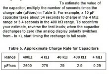
If you look at the table in my previous post, there are special instructions for the larger capacitors.
I ordered a $20 unit from Amazon and it will be here Monday.
The cap can has the electrolytics in right? The other caps are film?
I want to keep it as original as possible.
I ordered a $20 unit from Amazon and it will be here Monday.
The cap can has the electrolytics in right? The other caps are film?
I want to keep it as original as possible.
Anything with high capacitance (generally over 1 uF) is probably an electrolytic. I see a few of those in the schematic
You *can* test them for leakage, but this requires a tester capable of putting the rated voltage on them. So 3-500v. These are a bit harder to find these days, so better just to assume they are leaky.
You *can* test them for leakage, but this requires a tester capable of putting the rated voltage on them. So 3-500v. These are a bit harder to find these days, so better just to assume they are leaky.
I see these Mod Caps
and these Sprague Atoms
They are really cheap. I have also seen some for $18 when looking around.
I have searched for an answer, but I really don't know what I'm looking for to replace the 50uF 75VDC filter caps? The Mod caps are only 65 cents and the Sprague is $5. Is it a case of "you get what you pay for"? Thanks
edit: I got my cheap capacitor checker and I got readings of 77uF and 68uF and the little one measured .018. So maybe it's good for something if they are obviously faulty.
Last edited:
I've read that it's okay to go up in voltage, but could you tell me why I should increase capacitance as well? When I buy another amp to match am I going to need to put the same capacitors in for them to sound the same? Thank you
More bias uF -> less hum in the half wave rectified bias supply, which connects directly
to the output tube grids. And it's really hot inside that amp, you want good caps there.
I'd do that in both amps, if you don't like hum.
And replace that selenium rectifier (with a silicon diode and a 1k series resistor) before it fails,
it's toxic.
to the output tube grids. And it's really hot inside that amp, you want good caps there.
I'd do that in both amps, if you don't like hum.
And replace that selenium rectifier (with a silicon diode and a 1k series resistor) before it fails,
it's toxic.
Last edited:
Here's what I think I need.
2)100uF 200V Caps
1)1N4007-T Diode
1)1K 5W resistor Not sure about this one. Picked a 5 watt wire wound for the diode circuit.
1)18K 3W Metal Oxide
1)1K 3W Metal Oxide
1)6.8K 3W Metal Oxide
How does that look?
While doing my searching I see some folks are using a 6.8K ohm resistor in the diode circuit. What is the reason for this? TIA
That 100uF 200V cap should be just 100V, that was a typo.
The diode resistor can be just 1k 1W.
The 18k can be just 1W.
The 1k can be just 1W.
The 6.8k is good at 3W.
The series diode resistor adjusts the raw bias voltage more like the selenium diode voltage.
There is a chance that you 'll need to change the value of the diode resistor if you
can't get the bias current high enough, it depends on the output tubes.
If the pot needs to be pretty high up, try a 2k 1W or a 3k 1W instead.
Last edited:
That 100uF 200V cap should be just 100V, that was a typo.
The diode resistor can be just 1k 1W.
The 18k can be just 1W.
The 1k can be just 1W.
The 6.8k is good at 3W.
Okay. I replaced the components except for the rectifier because I wanted to see if it functioned and I am unclear on what to do. I powered it up with a variac, but I get no bias voltage. It plays music, so I'm sure I am doing something wrong. I have the positive lead on my meter connected to the terminal that says 1.56 Bias and the negative lead to chassis ground. I tried switching the ranges, to no avail. Any thoughts on this? I have some EL34's I could put in there as a test. TIA
I got it all set!
I couldn't understand why I wasn't getting any voltage on pin 6 of the output tubes when the amp was working. I kept checking my meter(Fluke 87), by switching it to ohms and touching the leads. I figured out how to put the diode in, still nothing. Come to find out after hours of checking and rechecking, my Fluke 87 meter is on the fritz. I have to squeeze where the dial is for it to register when it's on DC volts. I ended up leaving the 3K resistor in there, since it was in there when the meter started working. The bias screw is about in the middle with it adjusted.
It's working good. I am using my AVR as a preamp.
While I'm waiting to find a match for it, I bought an ST-70 that's supposed to be a one owner. So I'll probably have more questions.🙂
You guys have been a great help! I couldn't have done it without this forum and @rayma. Is there somewhere to donate?
Once again, thank you so much for bearing with me! I attached a picture of it sitting on top of my receiver for now.
- Home
- Amplifiers
- Tubes / Valves
- Noob..........