Newbie designing a 10W class AB Hybrid
(Yes, I know it has tubes but given the topology I hope this fits best here.)
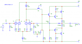
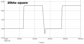
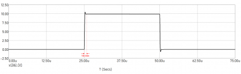
Hello kind people, I'm just looking for a bit of a sanity check on this design. I was shooting for 10W output in class AB, using ECC84/6N14P tubes as a front end since I have a few hanging around. It seems to simulate well, but I'm a complete novice so please let me know if you spot any mistakes, or just throw an opinion in. The main thing I'm looking for is squishing the overshoot on the falling edge of the square wave, throwing capacitance at it doesn't work.
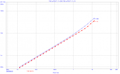
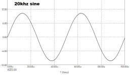
One other thing, are there any specific simulations I should be running? I've run a few and attached them, but are there anything I should be doing specifically? e.g. THD at Y frequency and Z amplitude etc.
Many thanks!
(Yes, I know it has tubes but given the topology I hope this fits best here.)
Hello kind people, I'm just looking for a bit of a sanity check on this design. I was shooting for 10W output in class AB, using ECC84/6N14P tubes as a front end since I have a few hanging around. It seems to simulate well, but I'm a complete novice so please let me know if you spot any mistakes, or just throw an opinion in. The main thing I'm looking for is squishing the overshoot on the falling edge of the square wave, throwing capacitance at it doesn't work.
One other thing, are there any specific simulations I should be running? I've run a few and attached them, but are there anything I should be doing specifically? e.g. THD at Y frequency and Z amplitude etc.
Many thanks!
Attachments
Last edited:
Hi Boulder!
R10 and R11 should be smaller, less than 200 Ohm or so.
Cut R9 in two and bootstrap (connect a cap from midpoint to output) Looks good! Good luck!
Thorsten
R10 and R11 should be smaller, less than 200 Ohm or so.
Cut R9 in two and bootstrap (connect a cap from midpoint to output) Looks good! Good luck!
Thorsten
Last edited:

Thanks very much Thorsten, I've made the changes you've suggested and it's working well , that was a great help.
In the meantime, I've been trying to make a few small improvements, namely to the load of the shunt cascode and the feedback compensation. I believe R8 could be replaced by a CCS, and Q1 might work better as a darlington pair. This should increase open-loop gain and therefore reduce distortion.
Currently, the only compensation in place is C3, but making the above changes results in instability, and simply increasing the capacitance of C3 results in an even slower falling edge. Perhaps there is a more elegant way? This will keep me busy for the next few days at least.
Thanks again
Last edited:
To be honest, if you don’t know how to calculate loop gain and unit gain bandwidth, you probably should not start to design amp. In general, if VAS has gain, not a simple cascode, you need Miller compensation.
Last edited:
Tubes take about 10 seconds to warm up when you switch on the amp. During warming up, you may not get enough current or any current out of the tubes.
To address this, you need a delay circuitry to preheat the tube. Another option is to only ac couple into the output stage, so that output stage will not be latched up to the power rail during tubes warming up.
To address this, you need a delay circuitry to preheat the tube. Another option is to only ac couple into the output stage, so that output stage will not be latched up to the power rail during tubes warming up.
Plot thd residual with res() function and test at 10 kHz with enough current to turn off one output transistor.
Not sure sanity and hybrid really go together in my world 🙂, as solid-state front end should easily outperform, but one observation:Hello kind people, I'm just looking for a bit of a sanity check on this design.
R6 and R7 can be reduced in size to directly reduce noise. 560 and 5k6 are worth trying. C2 will also need scaling to match.
You make a fair point, and it would also simplify design significantly, but there's a certain sentimentality tubes have that I'm fond of.Not sure sanity and hybrid really go together in my world , as solid-state front end should easily outperform
Thanks for that, am I correct in understanding that is because larger resistor values introduce more noise? I have tried to reduce them but it gets to the point that C2 would need to become a bipolar electrolytic to provide the needed capacitance.R6 and R7 can be reduced in size to directly reduce noise. 560 and 5k6 are worth trying. C2 will also need scaling to match
I was planning on implementing one already for this reason, but thank you for emphasising this.Tubes take about 10 seconds to warm up...you need a delay circuitry to preheat the tube
Wow, that's a really useful function, thank you for bringing it to my attention. Is there anything I should specifically looking for, or is it just an easy measure of the amount of crossover distortion?Plot thd residual with res() function and test at 10 kHz with enough current to turn off one output transistor.Plot thd residual with res() function and test at 10 kHz with enough current to turn off one output transistor.
My apologies, I had a plot and completely forgot to post it. I've made some fairly extensive modifications to the circuit, but I'll rerun the simulations and post them.To be honest, if you don’t know how to calculate loop gain and unit gain bandwidth, you probably should not start to design amp
Last edited:
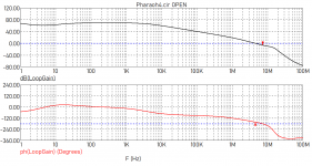
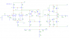
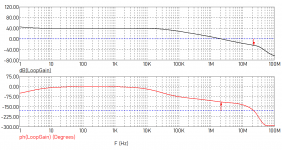
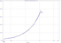
Here's the above mentioned modified schematic, without any compensation thus far, and it's associated stability plot. I've been a little busy but I'll finish the compensation and upload some more simulations when I can.
Attachments
Last edited:
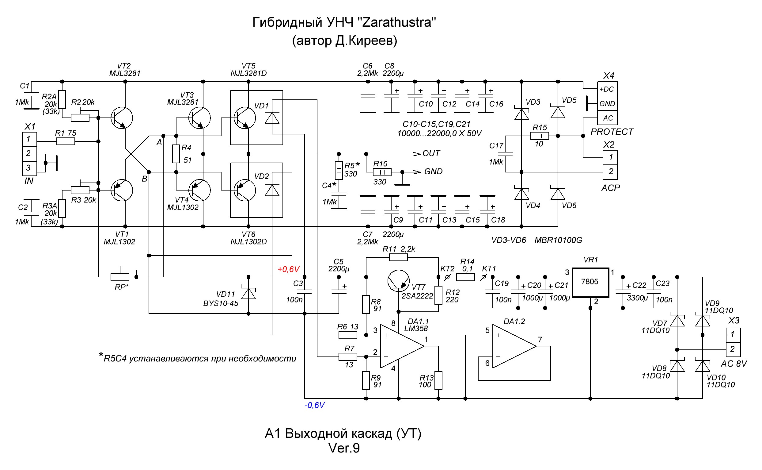
A very popular DIY hybrid in Russia https://www.diyaudio.com/forums/solid-state/364747-zarathustra-hybrid-amp.html#post6456298
Last edited:
Here's the above mentioned modified schematic, without any compensation thus far, and it's associated stability plot. I've been a little busy but I'll finish the compensation and upload some more simulations when I can.
Suggestions
1. You don't need Q1 and Q2. Just use a pair of resistors to connect from the emitters of Q4 and Q5 to 100v, to get the current value you want.
2. R10 and R14 are too big. They may "eat" too much voltage. 100 Ohm is a better value.
3. Don't rely on stray capacitance to compensate the amp. Add actual cap instead. You need compensation. Check the tube's datasheet, find the transconductance of the tube, put a shunt cap on VAS output. You need to learn how to calculate the loop gain and unit gain bandwidth, and calculate the value of the cap to compensate, instead of looking at the simulation graphic.
Last edited:
Here's the above mentioned modified schematic, without any compensation thus far, and it's associated stability plot. I've been a little busy but I'll finish the compensation and upload some more simulations when I can.
And more:
4. You don't need Q6 and Q7. Put them there won't make anything better.
5. Feedback resistor can be even smaller. R13 contributes to noise floor (white noise). Suggest 1K or below.
1. You don't need Q1 and Q2. Just use a pair of resistors to connect from the emitters of Q4 and Q5 to 100v, to get the current value you want.
I tried this, but ended up with a big current mismatch between the halves of the LTP and it caused a DC offset of about 2 volts through the output stage
3. Don't rely on stray capacitance to compensate the amp. Add actual cap instead. You need compensation. Check the tube's datasheet, find the transconductance of the tube, put a shunt cap on VAS output. You need to learn how to calculate the loop gain and unit gain bandwidth, and calculate the value of the cap to compensate, instead of looking at the simulation graphic.
My fault, I intended to compensate it and just didn't have the time, I've now rectified this.
2. R10 and R14 are too big. They may "eat" too much voltage. 100 Ohm is a better value.
4. You don't need Q6 and Q7. Put them there won't make anything better.
5. Feedback resistor can be even smaller. R13 contributes to noise floor (white noise). Suggest 1K or below.
All implemented, many thanks for the pointers. Point 5 means the feedback capacitor will have to be an electrolytic, I don't think this will cause any problems.
Attachments

You have output capacitor C4. You probably don't care the DC offset at output. Thus, you can omit the feedback capacitor C2.
Also don't forget to bootstrap R14 or use current source.
And also parallel a reversed diode to the base-emitter of Q4 and Q6 for each, to protect them the potential reversed Vbe.
Also don't forget to bootstrap R14 or use current source.
And also parallel a reversed diode to the base-emitter of Q4 and Q6 for each, to protect them the potential reversed Vbe.
Last edited:
I'm not worried about DC offset for the output, but 2v is enough for increased distortion at full power due to hitting one of the rails. Also one transistor is shut off at idle, though I'm not sure how much of an issue that is. Missing bootstrapping is a silly mistake, you can see it's there in previous schematics and I just missed it out accidentally in this one
When tubes age, they drift. DC coupling of tubes to transitor output stage is best avoided. Keep them seperate. You still get the tube sound - but the power of transistor output. Better bass and lower parts cost. A good example is here: Mugen: A Hybrid Audio Amplifier | Elektor Magazine
Or watch my talk from BAF 2019 here:
Denis Vilfort BAF 2019 Final - YouTube
Good luck!
Or watch my talk from BAF 2019 here:
Denis Vilfort BAF 2019 Final - YouTube
Good luck!
A Hybrid Audio Amplifier | Elektor Magazine[/url]
only for green/gold members...
When tubes age, they drift. DC coupling of tubes to transitor output stage is best avoided. Keep them seperate. You still get the tube sound - but the power of transistor output. Better bass and lower parts cost. A good example is here: Mugen: A Hybrid Audio Amplifier | Elektor Magazine
Or watch my talk from BAF 2019 here:
Denis Vilfort BAF 2019 Final - YouTube
Good luck!
Many thanks, I'll have a look at that later. I believe in the case of this schematic due to the ac coupled output and DC feedback it should self correct for any drift but I will keep it in mind
- Home
- Amplifiers
- Solid State
- Noob designing a 10W class AB Hybrid