Hi, I'm looking to use non-inductive resistors in the signal path from the amp to an RTR ESR6 treble unit to reduce the treble output so it better matches my speakers (KLH Nine electrostats). If anyone reads this and can help or make a suggestion -- How would I determine the proper resistance to get a proper match. Note-- there is a potentiometer on the tweeter to tweak the levels so the match doesn't have to be perfect. I'm hoping to get a 1/3 to 1/2 db reduction.
Hi, I'm looking to use non-inductive resistors in the signal path from the amp to an RTR ESR6
treble unit to reduce the treble output so it better matches my speakers (KLH Nine electrostats).
I'm hoping to get a 1/3 to 1/2 db reduction.
The built-in level control has much more of an adjustment range than a fraction of a dB.
You may be better off raising the crossover frequency, since it's around 2k right now.
Last edited:
For whatever reason the potentiometer doesn't seem to do much at all -- though I'm not using the built in crossover. It changes the levels but to a very minor degree.
I've read of people raising the crossover frequency with this particular unit. What approach would you recommend? And if you could recommend actual resistor values, that would be hugely helpful. Thank you.
I've read of people raising the crossover frequency with this particular unit. What approach would you recommend? And if you could recommend actual resistor values, that would be hugely helpful. Thank you.
Also note, there are two versions of KLH nines -- a version (mine) with just bass panels and a tweeter. And a three panel version with mid panels as well. Given that mine are the former, and I've deactivated the tweeters, I think may make sense to use the existing crossover frequencies of the ESR 6's. I don't have any means to test the frequencies at this point but I believe on both the Nines and the ESR 6's its around 1500k.
Placing a resistor in series with the ESL panels will result in a low pass filter response. If you want to attenuate the signal, place a capacitor in series with the ESL panel and this will attenuate the signal independently of frequency. Measure the ESL panel capacitance, then try a value 10X for the series C. This would give 20 log [C Series/(C Series + C ESL)]= 20Log [10/(10+1)] = 0.83dB attenuation. A series C equal to the ESL capacitance would provide 6dB attenuation. You will also need to bypass this series C with a high value resistor (say 20M) to provide a path for the high voltage DC bias reach the stator since the C will block the DC. The series C and the bypass Resistor will need to be HV types (probably rated for 3kV at least...higher would be better).
I've read of people raising the crossover frequency with this particular unit. What approach would you recommend?
I do know that they sound much better with the crossover point raised an octave or more. Much smoother sounding.
This could be done with a line level external crossover if you use one. Fiberglass behind the panels inside the cabinet helps as well.
Last edited:
For whatever reason the potentiometer doesn't seem to do much at all -- though I'm not using the built in crossover. It changes the levels but to a very minor degree.
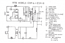
As several people already mentioned, adding a resistor in series with the audio signal to the ESL is not recommended because it will roll off top end response. The best way to adjust the SPL is to vary the HV bias. Looking at the attached schematic, the potentiometer would probably only change the SPL level about +/- 1dB. This is a very minor amount, but seems to agree with the markings on the back panel.
I’m not sure how much you are needing to drop the level…you mentioned 1/3dB and 1/2dB in the original post which would barely be noticeable, and the potentiometer changes the level more than that.
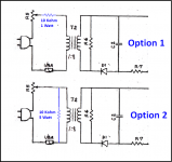
The last attachment shows two options for adding some additional adjustment range.
Option 1 would drop the level about -3dB, and retain the +/- 1 dB adjustment range.
Option 2 would also drop the level about -3dB, but the adjustment range would be increased to +/- 3dB.
Note that level adjustment will not be instantaneous…it may take 30 seconds to a minute to take full effect.
Attachments
Thank you all for the help.
To clarify, I meant reduce the output by 1/3 to 1/2 of the amount presently produced by the RTR units.
Thank you for the math - which I'll have to spend a bit of time looking at in order to understand - as well as the schematics. I've used a Behringer Ultracurve and found that dropping the HF around 6-8db is a solution though I would prefer to not have to use this additional unit. Perhaps the second modification would get me pretty close and I could achieve any additional reduction needed with some open cell foam -- which would also help with beaming in theory I guess (an issue with these tweeters).
Also as a side note, I'm considering reorienting the tweeter units in the RTR unit to a linear array (stacked vertically one after the next. I've read of someone doing this and preferring over the original orientation as RTR has it set up which to me seems kind of arbitrary though I get what it's trying to achieve. The fact that its deeply inset into the box is whats most questionable about the design.
Thank you for the help.
I’m not sure how much you are needing to drop the level…you mentioned 1/3dB and 1/2dB in the original post which would barely be noticeable, and the potentiometer changes the level more than that.
To clarify, I meant reduce the output by 1/3 to 1/2 of the amount presently produced by the RTR units.
Thank you for the math - which I'll have to spend a bit of time looking at in order to understand - as well as the schematics. I've used a Behringer Ultracurve and found that dropping the HF around 6-8db is a solution though I would prefer to not have to use this additional unit. Perhaps the second modification would get me pretty close and I could achieve any additional reduction needed with some open cell foam -- which would also help with beaming in theory I guess (an issue with these tweeters).
Also as a side note, I'm considering reorienting the tweeter units in the RTR unit to a linear array (stacked vertically one after the next. I've read of someone doing this and preferring over the original orientation as RTR has it set up which to me seems kind of arbitrary though I get what it's trying to achieve. The fact that its deeply inset into the box is whats most questionable about the design.
Thank you for the help.
I agree, Option 2 would be a good starting point. If you need a bit more reduction, you can always add the series resistance from Option 1 as well. Once you know what you need, values for the resistors can be calculated to provide that center level, with some adjustment available either side of center.I've used a Behringer Ultracurve and found that dropping the HF around 6-8db is a solution though I would prefer to not have to use this additional unit. Perhaps the second modification would get me pretty close and I could achieve any additional reduction needed with some open cell foam -- which would also help with beaming in theory I guess (an issue with these tweeters).
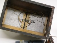
As rayma mentioned, the RTR tweeter panels can sound a bit strained in their bottom octave when listening at higher levels. Adding some thin acoustic damping material to the back of each panel like Janszen did solves this problem. Some thin crafting felt works well, to damp the diaphragm resonance modes causing the problem.
Attachments
- Status
- Not open for further replies.
- Home
- Loudspeakers
- Planars & Exotics
- Non-inductive resistor to reduce treble output of RTR ESR6