It's worth considering Crystek clock has internal ceramic decoupling
cap. IMO these are not good for sound even though they are theoretically
best option for low impedance decoupling.
Its no where near the analogue signal so is not going to have any effect on the sound quality!
For the record there are two types of ceramic dielectrics, class 1 NP0/COG and class 2, X7R etc. Class 1 are one of the most stable dielectrics available and would have no detrimental effect on the sound even if used in the signal path...
Rickmcinis, you could use my full name... All I have done is put up facts from the real world of electronics where we have to make things work and work correctly, not play, it is sound advice, your choice not to listen and learn.
I cannot keep up with the on again off again permission of using a name.
I am dealing with an even "realer" world than you since I am speaking of something I have done.
You have no experience using this battery and you have no interest in trying out this scheme.
You are extrapolating from your experience with the hope that it works for everything and it may but it is just as likely it does not. I am of the opinion that just because the bypass capacitor is required when using a regulator it does not follow that the A123 26650 requires the use of them.
I am not giving anyone advice. I am telling people what I have done and suggest they give it a try. It is not that big of a deal. If you think the lack of the bypass cap will cause damage please explain what the damage will be. I can only imagine the potential for electrocution or destruction of one's device would be the only things deserving of such high dudgeon.
You are the one giving advice (with a stern warning added).
If you do not like what you hear without the bypass you put the cap back.
How do we get anywhere if nothing is tried? And to repeat I am far from the first person to have used this and find it works very well. I did not come up with the idea. My ego is not involved.
If no one tries anything this site becomes a recipe book. Not very interesting.
I wish I could understand the intensity of your need to comment on something you know nothing about. You have never used this battery, you know nothing about it and yet you berate me as stupid for telling anyone who elects to read my post what I hear.
If anyone refuses to listen it is you. I listen intently to my system and know its foibles well. If the lack of bypass caps made the system worse I would return them immediately.
Remember I know that bypass caps are necessary after a regulator and should be placed "at" the circuit. I cannot learn this again, I already know it.
On the other hand you have no interest in trying this since you"know" it will not work. Who is being the know-nothing here?
I have no opinion on any audio advice until I try it for myself. I try to limit myself to posting about things for which I have experience.
Just ran some z-tests on A123 cylindrical cells which are "aged" -- the impedance is in the tens of ohms. I think the datasheet said 0.006 ohms was typical.
One of the ham-radio blogsters complained that LiFePO4 cells do not age gracefully.
More work to be done.
One of the ham-radio blogsters complained that LiFePO4 cells do not age gracefully.
More work to be done.
I cannot keep up with the on again off again permission of using a name.
I am dealing with an even "realer" world than you since I am speaking of something I have done.
You have no experience using this battery and you have no interest in trying out this scheme.
You are extrapolating from your experience with the hope that it works for everything and it may but it is just as likely it does not. I am of the opinion that just because the bypass capacitor is required when using a regulator it does not follow that the A123 26650 requires the use of them.
I am not giving anyone advice. I am telling people what I have done and suggest they give it a try. It is not that big of a deal. If you think the lack of the bypass cap will cause damage please explain what the damage will be. I can only imagine the potential for electrocution or destruction of one's device would be the only things deserving of such high dudgeon.
You are the one giving advice (with a stern warning added).
If you do not like what you hear without the bypass you put the cap back.
How do we get anywhere if nothing is tried? And to repeat I am far from the first person to have used this and find it works very well. I did not come up with the idea. My ego is not involved.
If no one tries anything this site becomes a recipe book. Not very interesting.
I wish I could understand the intensity of your need to comment on something you know nothing about. You have never used this battery, you know nothing about it and yet you berate me as stupid for telling anyone who elects to read my post what I hear.
If anyone refuses to listen it is you. I listen intently to my system and know its foibles well. If the lack of bypass caps made the system worse I would return them immediately.
Remember I know that bypass caps are necessary after a regulator and should be placed "at" the circuit. I cannot learn this again, I already know it.
On the other hand you have no interest in trying this since you"know" it will not work. Who is being the know-nothing here?
I have no opinion on any audio advice until I try it for myself. I try to limit myself to posting about things for which I have experience.
Firstly learning some basics of what you are doing is what I would do whatever I was going to do...
I have far more experience of battery powered products than you do, both audio and non-audio, so my comments are from as I said the real world of electronics where things are tested extensively both with measurements, which are critical and in the case of audio based products proper controlled listening tests. Funny I have over 35 years experience in this field, I have also played about with audio and audio reproduction for many of those years as well as playing in bands in my dim and distant past, so I am not talking about stuff I have not tried or investigated in the past. And my beliefs have changed due mainly to using controlled listening tests in conjunction with this hobby.
So maybe you should step back from your superior attitude and learn like many others have, that sighted listening and playing is not the way to go, as your perceptions cant be trusted... Learning and doing things properly will give far better results, but whatever I wright you will ignore.
Have fun with your playing.
As to bypass capacitors I am talking about the bypass capacitors next to a devices power pins... as well as a complete power delivery system, that needs capacitors or some additional capacitance to provide the required power.
Just ran some z-tests on A123 cylindrical cells which are "aged" -- the impedance is in the tens of ohms. I think the datasheet said 0.006 ohms was typical.
One of the ham-radio blogsters complained that LiFePO4 cells do not age gracefully.
More work to be done.
I would be glad to send you one that isn't tired to test.
I think the continuous charging allows the batteries to stay fresh as opposed to cycling.
So far, after a couple of years in service, I have not noticed any loss of performance but only substituting new ones would make that meaningful.
Might you measure them on the output of a regulator? Just hoping ...
No question the battery you tested could not possibly do a good job at powering anything other than a flashlight!
I figure the key to them is their extraordinary ability to deliver bursts of current "faster" than the regulator preceding them?
I am the one with a superior attitude? Relaying my experience is display of a superior attitude?
So you going on about your 35 years of experience, which I do respect and appreciate, and your unwillingness to try something because you KNOW it is wrong is something other than a "superior" attitude.
There must be more of a language barrier between our countries than I would have ever thought.
At this point I will hope Mr. Walton will test the scheme and settle this. That will be a verdict both of us will have to accept.
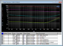
Some impedance data -- bypassing helps a little. These were newer LiFePO4's which I just charged.

If I may assume you misunderstood what I said.
The scheme I am talking about is using the regulator to keep the battery charged at all times. The battery is essentially an output capacitor.
This way you have a constant voltage and I suspect makes life easy for the battery with no cycling.
If you ever have nothing better to do, and I know that is not likely, I am hoping you might rig up something like this and see what your meters have to say.
If you have a DAC around that uses 3.3 volts and an easily removed bypass cap it would be interesting to hear what you think of the sound with and without the bypass cap. Assuming the battery is as close to the circuit as possible.
My customers are always telling me it never hurts to ask so forgive me for following in their footsteps with my begging.
Take care,
If I may assume you misunderstood what I said.
The scheme I am talking about is using the regulator to keep the battery charged at all times. The battery is essentially an output capacitor.
This way you have a constant voltage and I suspect makes life easy for the battery with no cycling.
If you ever have nothing better to do, and I know that is not likely, I am hoping you might rig up something like this and see what your meters have to say.
If you have a DAC around that uses 3.3 volts and an easily removed bypass cap it would be interesting to hear what you think of the sound with and without the bypass cap. Assuming the battery is as close to the circuit as possible.
My customers are always telling me it never hurts to ask so forgive me for following in their footsteps with my begging.
Take care,
Rick
Can you show us a pic of your arrangement, ie; battery location, wires to
DAC etc.
Also are you connecting reg OP directly to battery? In this case you are
getting combination of reg + battery. You need to isolate reg OP from battery
with a small resistor based on the average current draw.
cheers
T
Battery powered DAC
I have read all the posts on this thread with interest as I have been trying out powering one of my DACs by battery.
The first thing I have to say is I have tried various ADM7150 and LT3042 and other lower noise regulator power supply kits but none of them get close in terms of sound quality to a LiFePo4 battery.
The second thing is what Rick says about capacitors on the power rails between the battery and chip doing more harm than good is absolutely correct. The improvement in sound quality after they have been removed is not subtle at all - clearer mids, deeper bass, cleaner top end, wider soundstage etc.
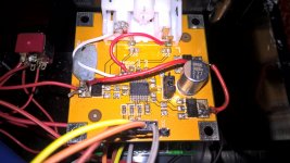
The DAC in the pictures is what most people would call a budget option, but when powered by a A26650 battery, the sound quality is anything but. I am using DIYINHK CM6631A USB->I2S board (£40) paired with a very cheap PCM5102A board (£5 each) both powered by separate A26650 batteries which are float charged by a couple of AMS1117 regulator modules (£1.50 each) which gets its 5V power from the USB->I2S board USB pin. There is dual pole switch between the batteries 3.3v+ and the boards so the power can be cut when not in use
The USB board has been left as is, but on the PCM5102A which is designed to be powered by 5-9v, there are 3 AMS1117 regulators to which one of the batteries 3.3v+ is fed in a daisy chain configuration. After each regulator there was a 10uf and 0.1uf capacitor feeding pins 1,8 and 20 of the chip. These have been removed. In addition the low pass filter (470R & 2N2 cap) on the analogue outputs have been removed so the chip output is wired directly to the phono sockets. Any noise is not audible during normal playback.
The float charge boards are permanently wired to the batteries, but the sound quality of DAC does not change if you remove them (i.e the chips draw all their power from the battery).
I have read all the posts on this thread with interest as I have been trying out powering one of my DACs by battery.
The first thing I have to say is I have tried various ADM7150 and LT3042 and other lower noise regulator power supply kits but none of them get close in terms of sound quality to a LiFePo4 battery.
The second thing is what Rick says about capacitors on the power rails between the battery and chip doing more harm than good is absolutely correct. The improvement in sound quality after they have been removed is not subtle at all - clearer mids, deeper bass, cleaner top end, wider soundstage etc.
The DAC in the pictures is what most people would call a budget option, but when powered by a A26650 battery, the sound quality is anything but. I am using DIYINHK CM6631A USB->I2S board (£40) paired with a very cheap PCM5102A board (£5 each) both powered by separate A26650 batteries which are float charged by a couple of AMS1117 regulator modules (£1.50 each) which gets its 5V power from the USB->I2S board USB pin. There is dual pole switch between the batteries 3.3v+ and the boards so the power can be cut when not in use
The USB board has been left as is, but on the PCM5102A which is designed to be powered by 5-9v, there are 3 AMS1117 regulators to which one of the batteries 3.3v+ is fed in a daisy chain configuration. After each regulator there was a 10uf and 0.1uf capacitor feeding pins 1,8 and 20 of the chip. These have been removed. In addition the low pass filter (470R & 2N2 cap) on the analogue outputs have been removed so the chip output is wired directly to the phono sockets. Any noise is not audible during normal playback.
The float charge boards are permanently wired to the batteries, but the sound quality of DAC does not change if you remove them (i.e the chips draw all their power from the battery).
Attachments

Hi,
Have you any cap or reg either between your A123 cell and the dac chip????
No voltage regulation of the cell ? it swing between 3.6 & 3.2 V according to the aging charge ?
I made this experiment only : trying between a C-Core and a single LifePO4 from A123 and a C-Core transformer : both with a TS7A reg after for a clock board and a FIFO board with Chrystek crystals, so the digital front end but not the power supply of the dac chip itself... I prefered the C-CORE which gave in my setup an as transparent sound but with more punch an low end !
Hi,
Have you any cap or reg either between your A123 cell and the dac chip????
Just a wire, the PCM5102a chip and the CM6631A board run from a 3.3V source which the batteries provide. No regulation or filtering of the supply is needed in between.
Hi bjd,
Interesting try-out you've made - I have a few comments that I hope may be constructive in this context ...
I once tried something similar - I only decoupled the PCM1794 I was using with some electrolytics I've found to sound very good. And I played with this for some time, and I reckon that it actually sounded quite well. However, eventually I got around to measuring the noise across the capacitors (I think they were Ø 10 mm types and thus could not all be placed close to the PCM1794) and it was on the level of several mVs and lots of HF components.
The thing is that the DACs switch power into their system in an on/off manner and this creates quite high frequency noise components that may radiate into the other parts of the circuitry if not "shunted"/decoupled. If you have access to e.g. a 100 MHz oscilloscope I might suggest you try measuring the noise (in the probe's x10 position) on the PSU pins - it will be huge without decoupling. My guess would be 50 - 100 mVs at higher frequencies where the batteries essentially are not decoupling.
My guess would also be that a reason why your DAC sounds better without the decoupling capacitors could be because these capacitors do not sound well (or possibly measure well). In my experience there can be very significant differences between capacitors and capacitor brands and so selecting the right ones may make (all) the difference.
Personally I've found that Kemet and TDK C0G 1206 SMD capacitors (100 nF - highest possible voltage. Available e.g. from Mouser) may be feasible for close-to-the pins decoupling. A little farther from the pins I typically use radial electrolytics like e.g. Rubycon ZL or Nichicon KZ (very round sounding) ... but there's a whole thread here on diyaudio dealing with "best electrolytic capacitors" - many opinions.
I have not heard nor measured the PCM5102 but my guess here would be that without the decoupling there's also quite some HF noise on the output. This may not be an issue (depending on your system), however, personally I've found that in the long term it leads to listening fatigue .. well, just an observation.
A few comments that popped up when I saw your post - good luck in your endeavors 😉
Jesper
Interesting try-out you've made - I have a few comments that I hope may be constructive in this context ...
The second thing is what Rick says about capacitors on the power rails between the battery and chip doing more harm than good is absolutely correct.
I once tried something similar - I only decoupled the PCM1794 I was using with some electrolytics I've found to sound very good. And I played with this for some time, and I reckon that it actually sounded quite well. However, eventually I got around to measuring the noise across the capacitors (I think they were Ø 10 mm types and thus could not all be placed close to the PCM1794) and it was on the level of several mVs and lots of HF components.
The thing is that the DACs switch power into their system in an on/off manner and this creates quite high frequency noise components that may radiate into the other parts of the circuitry if not "shunted"/decoupled. If you have access to e.g. a 100 MHz oscilloscope I might suggest you try measuring the noise (in the probe's x10 position) on the PSU pins - it will be huge without decoupling. My guess would be 50 - 100 mVs at higher frequencies where the batteries essentially are not decoupling.
My guess would also be that a reason why your DAC sounds better without the decoupling capacitors could be because these capacitors do not sound well (or possibly measure well). In my experience there can be very significant differences between capacitors and capacitor brands and so selecting the right ones may make (all) the difference.
Personally I've found that Kemet and TDK C0G 1206 SMD capacitors (100 nF - highest possible voltage. Available e.g. from Mouser) may be feasible for close-to-the pins decoupling. A little farther from the pins I typically use radial electrolytics like e.g. Rubycon ZL or Nichicon KZ (very round sounding) ... but there's a whole thread here on diyaudio dealing with "best electrolytic capacitors" - many opinions.
In addition the low pass filter (470R & 2N2 cap) on the analogue outputs have been removed so the chip output is wired directly to the phono sockets. Any noise is not audible during normal playback.
I have not heard nor measured the PCM5102 but my guess here would be that without the decoupling there's also quite some HF noise on the output. This may not be an issue (depending on your system), however, personally I've found that in the long term it leads to listening fatigue .. well, just an observation.
A few comments that popped up when I saw your post - good luck in your endeavors 😉
Jesper
My guess would also be that a reason why your DAC sounds better without the decoupling capacitors could be because these capacitors do not sound well (or possibly measure well). In my experience there can be very significant differences between capacitors and capacitor brands and so selecting the right ones may make (all) the difference.
Jesper
I have no doubt the components removed were of a very low quality including the analogue low pass filter, but to quote the datasheet "Compared with many conventional switched capacitor DAC architectures, the PCM510xA family offers up to 20 dB lower out-of-band noise, reducing EMI and aliasing in downstream amplifiers/ADCs, measured from the traditional 100-kHz OBN measurements to 3 MHz)."
I believe the same than Jespers .
The LifePo4 of a good brand should have a very low ESR : far lower than a KZ cap for instance which on the paper is good for audio as also not a Noisy power source from the plug wall... but the fact is than with the length of the wires bettween the "long" tube cell it can not be as close as a reservoir cap near the load. So ESR should rise !
Did you have a ceramic smd capacitor before removing it ?
If you want Something very transparent you may try for instance a Nichicon ES bi-polar cap on the leads of the dac chip (power + gnd) to test if it helps without deterioration of the sound but with deeper or tighter low end ?!
Basicly it's good to trust his ears 🙂
Did you have a ceramic smd capacitor before removing it ?
99% sure they were ceramic, unlikely to be film type for a £5 board.
Read post #45 until you understand by heart.
No i have not measured battery noise, but when it comes to DAC chip voltage level is utterly important. Battery is ok but use a voltage regulator afterwards. Most noise is from the DAC itself when we talk about 18bit resolution, at 24dB you have past the limits of what you can design. To be really serious you can try what i have done, but this requires lots of practice before you start experimenting on your expensive DAC chip.
The leads from your decoupling cap has inductance of approx 1nH/mm this means that if you have the worlds most quiet power source and 5cm wire widely spaced you end up with 100 to 500nH... nice resonace circuit together with capacitance on the circuit board and the caps.
So the trick is to get the biggest capacitor with shortest possible leads. And that is SMD capacitor 0306 reversed geometry cap. Just wide enough to be standing on its short edge right on top of the legs on the DAC chip!
0,2to 0,3 mm lead length, that is.
I have found TDK 0306 4,7uF caps that i have managed to solder directly on the DAC chip. Not easy... they are 0,8mm times 1,6mm and the soldering surface is extremely small, you need SMD soldering iron, dentist binocular glasses, lots of light , and time, and practice. on PCM1796 and PCM1794 DAC there is 4 places to put those caps, legs: 8-9, 15-16, 23-24, 27-28. Buy 10 extra pieces to practice soldering skills.
I have done some dacs with this extreme (i would say) method and it´s worth the effort.
No matter how good power supply you have as i mentioned before, it´s right on the legs where it´s all matters in the end. You can´t get itt better unless you manage to put 2x4,7uF on each place... i have tried. Maybe i should post some pictures when I got time.
0306 size, that's awesome ! far above my skill and Tools either !
what about the inductance of a long cell LiFePo4 please ? Lost cause because the few centimeters width+ extra wires towards the load to power ?
ah yes post 45 from Marce ! Usually I write on the marble his advices, but sometimes the too big inductance between my two ears is like a bad memory cap !
what about the inductance of a long cell LiFePo4 please ? Lost cause because the few centimeters width+ extra wires towards the load to power ?
ah yes post 45 from Marce ! Usually I write on the marble his advices, but sometimes the too big inductance between my two ears is like a bad memory cap !
Last edited:
@Eldam:
Take a look here:
https://www.eeweb.com/toolbox/rectangle-loop-inductance
If you measure the lengths of the LiFePO4 cells together with the wire lengths you may get a quite good indication of the inductance present (being very precise may not be needed).
@esl63:
This tip originally is courtesy marce ... IMHO a superb PCB calculator e.g. for inductances and capacitances between traces and ground layers ...
https://www.saturnpcb.com/pcb_toolkit.htm
Cheers,
Jesper
what about the inductance of a long cell LiFePo4 please ? Lost cause because the few centimeters width+ extra wires towards the load to power ?
Take a look here:
https://www.eeweb.com/toolbox/rectangle-loop-inductance
If you measure the lengths of the LiFePO4 cells together with the wire lengths you may get a quite good indication of the inductance present (being very precise may not be needed).
@esl63:
... Have you by any chance tried to measure distortion on these capacitors? If I remember correctly X5R dielectrics may distort quite some, i.e. generate out-of-pulse noise.I have found TDK 0306 4,7uF caps that i have managed to solder directly on the DAC chip.
This tip originally is courtesy marce ... IMHO a superb PCB calculator e.g. for inductances and capacitances between traces and ground layers ...
The leads from your decoupling cap has inductance of approx 1nH/mm this means that if you have the worlds most quiet power source and 5cm wire widely spaced you end up with 100 to 500nH...
https://www.saturnpcb.com/pcb_toolkit.htm
Cheers,
Jesper
- Home
- Source & Line
- Digital Line Level
- Noise measurements for LiFePo4 and supercapacitors?