Hi, I am new here. Name is Tazz...
I have gone on a wild adventure to build a DJ mixer. So far so good. I have a main board with multiple balanced outs etc... Part of this PCB is a headphone section built on the LM386. I know I know not the greatest chip...
The headphones actually sound pretty good. But the problem is when I touch the pot or the cable or the caps of only the headphone section I get EMI or loud screeching sound. This only happens at this section the rest of the PCB is fine...
The PCB has and uses 100% ground layer...
Here are schematics pictures of the PCB. The problem capacitors are c21 and c22. If touch those we get the loud screetching sound. If I put the pot on the panel of the case and close the case, the case transfers the EMI to the headphones. Touching the jack of the headphones doesn't affect it nor the rest of the circuit.
Before I go down the route of redesigning PCBs just wondering if some insulation techniques could work.
Dropbox - mixer-files - Simplify your life
1. Is chassis connected to audio ground anywhere?
2. What's that RV3/RV6 1 meg trimmer business in front of the volume control all about?
3. Why did you leave out the bypass capacitors at LM386 pin 7? They will have lousy PSRR without those.
4. What are you using for a power supply?
5. Please twist your headphone output wires as well.
6. R9, 15, 21, 27 are redundant.
7. Only the LM386N-4 is actually rated for supply voltages exceeding 12 V.
"Not the greatest chip" potentially qualifies for understatement of the decade. LM386s are in no way, shape or form particularly hi-fi.
Yes correct. Actually using International power +-12V linear PSU and I have tried both the regular and the N-4
1- No, audio ground is not connected to chassis. Are you talking about taking any of the ground points on the PCB and attaching it to the chassis?
2- It was designed off a circuit I found in the net. So some thing likes the 1Meg pot probably not necessary. But it helps adjust the volume to a reasonable value for multiple headphones.
3- See number two that circuit didn't call for them. Is the bypass capacitor pin 7 for input noise? I can maybe ad hoc them on to the board.
4- International Power +-12v linear regulated.
5- Done. Makes no different touching the jack doesn't affect the sound.
6- Ok. I think that was combination of putting two circuits together...
7- Correct, using 12V And LM386. I also tried the LM386N-4 no difference.
Last edited:
So I ran a lead, from the closest ground to the LM386, to the case and the buzz/Humm is gone. I still get a bit of interference when I touch the pot, but if the knobs are on it's ok. If I touch c21 and c22 I still get a big buzz. But that's ok I suppose when the case is closed. Just hopefully if I do my cable management correctly inside the case nothing will touch those two caps.
Also properly screwing in the top pannel now the pots are properly grounded so no noise when I touch them...
> grounded so no noise
There's two rules in the Navy:
* If it moves, salute it
* If it doesn't move, paint it
There must be some similar concise way to say what to do with power, signals, grounds, and boxes.
There's two rules in the Navy:
* If it moves, salute it
* If it doesn't move, paint it
There must be some similar concise way to say what to do with power, signals, grounds, and boxes.
OK, now that the grounding is hopefully taken care of...
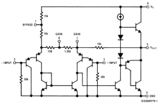
This is one of those cases where it pays to look at the equivalent circuit in the datasheet.

The input stage looks like a Darlington LTP job, but actually the left-hand half of it is merely being used to set up output DC levels and as a level-shifted ground reference, with the other half forming a current feedback amplifier. The trick to setting up output DC is employing a current mirror. Therefore the voltage over the 15k resistor between Vout and GAIN I is always going to be half that over the two 15ks on the left that are split by the bypass pin connection, and with no signal input, Vout becomes
Vout = V(+in) + 1/2 (Vs - (2Vbe - V(-in)))
or with V(+in) = V(-in) = 0 V:
Vout = 1/2 Vs - Vbe ~= 1/2 Vs - 0.6 V
This relation holds at both DC and AC, so that half of any power supply hum and noise voltage will find itself on the output as well. Hence output PSRR is all but 6 dB, for an effective input PSRR of 27 dB or so.
The bypass pin capacitor filters out AC components on the supply, so PSRR is much improved.
You can actually coax the LM386 into working sort of like a conventional voltage feedback opamp (I've played with it in simulation for a bit), but you'll have to wrestle some stability issues in exchange for markedly improved distortion performance.
I would recommend doing so.3- See number two that circuit didn't call for them. Is the bypass capacitor pin 7 for input noise? I can maybe ad hoc them on to the board.
This is one of those cases where it pays to look at the equivalent circuit in the datasheet.
The input stage looks like a Darlington LTP job, but actually the left-hand half of it is merely being used to set up output DC levels and as a level-shifted ground reference, with the other half forming a current feedback amplifier. The trick to setting up output DC is employing a current mirror. Therefore the voltage over the 15k resistor between Vout and GAIN I is always going to be half that over the two 15ks on the left that are split by the bypass pin connection, and with no signal input, Vout becomes
Vout = V(+in) + 1/2 (Vs - (2Vbe - V(-in)))
or with V(+in) = V(-in) = 0 V:
Vout = 1/2 Vs - Vbe ~= 1/2 Vs - 0.6 V
This relation holds at both DC and AC, so that half of any power supply hum and noise voltage will find itself on the output as well. Hence output PSRR is all but 6 dB, for an effective input PSRR of 27 dB or so.
The bypass pin capacitor filters out AC components on the supply, so PSRR is much improved.
You can actually coax the LM386 into working sort of like a conventional voltage feedback opamp (I've played with it in simulation for a bit), but you'll have to wrestle some stability issues in exchange for markedly improved distortion performance.
Attachments
Last edited:
Thanks! So far everything is good I don't have any "noise" issues. Everything sounds good in the headphones.
I'll probably redesign the headphone section at some point but for now it works as needed.
I'll probably redesign the headphone section at some point but for now it works as needed.
I remember the LM386 very well from about 1980.
My industrial electronics class all built one each.
Pretty much all 12 oscillated and blew up with recommended circuit !
Looking back the layouts weren't tight enough, the decoupling could be better and the zero volts line wasn't earthed.
My industrial electronics class all built one each.
Pretty much all 12 oscillated and blew up with recommended circuit !
Looking back the layouts weren't tight enough, the decoupling could be better and the zero volts line wasn't earthed.
Last edited:
- Home
- Amplifiers
- Headphone Systems
- Noise in headphone section of PCB.