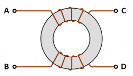
The YT video is blaming the hiss on high frequency PWM noise from the PAM8610 and is eliminating it by connecting a common mode choke between amp output and speaker.
That certainly looks well worth experimenting with.
That certainly looks well worth experimenting with.
Last edited:

Do you mean on the pam8610 and also the BT module?
Yes, I thought that the the signal from the BT module may be too large for the PAM amp.
However, the YT video seems to have identified the cause of your hiss problem.
I read That the PAM8610 is not the best amp to choose because of this problem.
Last edited:
hmmm, if you said so then I will try to recreate the experiment in the video and keep updating. Thank you for sticking with this problem with meYes, I thought that the the signal from the BT module may be too large for the PAM amp.
However, the YT video seems to have identified the cause of your hiss problem.
I read That the PAM8610 is not the best amp to choose because of this problem.
Yes, I thought that the the signal from the BT module may be too large for the PAM amp.
However, the YT video seems to have identified the cause of your hiss problem.
I read That the PAM8610 is not the best amp to choose because of this problem.
now I understand why people tend to choose the TPA3118 over the Pam8610 and why the pam is much smaller. it's because the TPA3118 have a couple of inductor and capacitor to filter out the signal
The common mode choke shown in the YT video may be an effective way to prevent the high frequency 'hiss' travelling from your amplifier output to speaker.
However, given the amount of experimentation required to get the choke just right, it might be a better idea just to buy a properly filtered Class D amp.
However, given the amount of experimentation required to get the choke just right, it might be a better idea just to buy a properly filtered Class D amp.
Attachments
 Moving this to Class D.
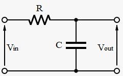
Adding a common mode choke to my setup was not helping at all, and the hissing even got louder. But I have tried another approach. By adding a capacitor and resistor in parallel, the hissing reduces to almost unhearable but if I stick my ear close to the driver I still can hear the hiss. But there is a downside, the sound quality is a little bit weird, and I think the bass is not as punchy as before, the treb is not as clear as before. I don't know what's wrong here.
By adding a capacitor and resistor in parallel... I don't know what's wrong here.
An RC filter can be used to attenuate treble or attenuate bass depending on whether it is the capacitor or the resistor which is in parallel with the load.
I doubt if a simple RC filter will help in your case.
You don't show how you are connecting the RC circuit or what the R and C values are. You are unlikely to succeed in reducing the hiss, while at the same time maintaining the sound quality, by working at random.
I suggest you cut your losses and replace your present unfiltered Class D amplifier module with a fully filtered one.
Attachments
Thank you for this new knowledge, and yes maybe getting a fully filtered amp board is the right choice here.An RC filter can be used to attenuate treble or attenuate bass depending on whether it is the capacitor or the resistor which is in parallel with the load.
I doubt if a simple RC filter will help in your case.
You don't show how you are connecting the RC circuit or what the R and C values are. You are unlikely to succeed in reducing the hiss, while at the same time maintaining the sound quality, by working at random.
I suggest you cut your losses and replace your present unfiltered Class D amplifier module with a fully filtered one.
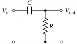
I can now be more helpful and give the circuit and component values for what is called a "half filter".
This is the same arrangement as the treble filter pictured above, but with an inductor in place of the resistor (see attachment).
C = 1 uF and L = 30 uH (micro henries) - These are the values for a 4 ohm speaker system.
I hope you get the problem sorted and continue to enjoy your adventures into the fascinating world of electronics. 😎
Attachments

Thank you for the solution, But I don't have the 1uf capacitor, will the 2.2uf work and which capacitor did you meanI can now be more helpful and give the circuit and component values for what is called a "half filter".
This is the same arrangement as the treble filter pictured above, but with an inductor in place of the resistor (see attachment).
C = 1 uF and L = 30 uH (micro henries) - These are the values for a 4 ohm speaker system.
I hope you get the problem sorted and continue to enjoy your adventures into the fascinating world of electronics. 😎
The capacitor value must be 1 uF* or the result will be unpredictable.
You must use a bipolar (non-polar or NP) electrolytic capacitor, so not the polar type you show on the right.
The film capacitor you show on the left is also bipolar and this would be my choice.
*By the way, two 2.2 uF capacitors connected in series would give you 1.1 uF.
You must use a bipolar (non-polar or NP) electrolytic capacitor, so not the polar type you show on the right.
The film capacitor you show on the left is also bipolar and this would be my choice.
*By the way, two 2.2 uF capacitors connected in series would give you 1.1 uF.
i have these bipolar capicitor and none of them is 1uf maybe i have to find it some where elseThe capacitor value must be 1 uF* or the result will be unpredictable.
You must use a bipolar (non-polar or NP) electrolytic capacitor, so not the polar type you show on the right.
The film capacitor you show on the left is also bipolar and this would be my choice.
*By the way, two 2.2 uF capacitors connected in series would give you 1.1 uF.
and just another dump question will the 33uh ok ?The capacitor value must be 1 uF* or the result will be unpredictable.
You must use a bipolar (non-polar or NP) electrolytic capacitor, so not the polar type you show on the right.
The film capacitor you show on the left is also bipolar and this would be my choice.
*By the way, two 2.2 uF capacitors connected in series would give you 1.1 uF.
i have these bipolar capicitor and none of them is 1uf maybe i have to find it some where else
I can't see their values, but remember that when wiring capacitors in parallel the capacitances add up.
e.g. 0.47 uF in parallel with 0.47 uF gives approximately 1 uF.
And, in answer to your last question, 33 uH should be close enough.
One piece of friendly advice, bibidentuhanoi, there is no need to quote all my posts. 🙂
In fact, the forum rules ask you not to do so, as it results in cluttered threads. 😎
In fact, the forum rules ask you not to do so, as it results in cluttered threads. 😎
A speaker does not respond to a common mode signal anyway.Adding a common mode choke to my setup was not helping at all,
So, after receiving all of my parts, I tried to assemble them according to your diagram, and without connecting the QCC, the noise was reduced to almost none, but it is still audible if my ear is close to the driver. When the QC is connected, however, the noise becomes louder. I also tried switching my setup to the TPA3110, and the results are better compared to the PAM8610. The noise level decreases even more. However, this configuration has the same problem as the previous one.I hope you get the problem sorted and continue to enjoy your adventures into the fascinating world of electronics. 😎
- Home
- Amplifiers
- Class D
- Noise ClassD PAM 8610 plus Bluetooth QCC3031 with TPA 6132A2