Hi Bimo,
Greetings!
Since you are technically minded, and you love the intellectual pursuit, you naturally will prefer this approach because it seems better to match the output with the input, BUT, a lot of people do like the monotonic harmonic reduction - like the tube amps, which mostly do not use much global feedback.
It's like food; some like sweet, some like savoury.........
Hugh
Hi Hugh,
What about very low distortion and monotonic harmonic distortio in the same time? Does second harmonic colour the sound if high enough and that was what many like?
Best weshies
Damir
Member
Joined 2009
Paid Member
I can't honestly say that I have heard enough amps whose distortion profile I know, to say that I believe in monotonic harmonics as being best. But what I've read, written by people are are widely respected, a monotonic profile is heartily recommended.
I have noticed that I like the sound of single ended tube amplifiers and the sound of Singleton input SS amplifiers.
I have noticed that I like the sound of single ended tube amplifiers and the sound of Singleton input SS amplifiers.
The double bootstrap it is something I like 😀
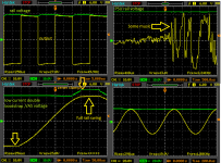
I have tested resistor (high current) and ''zener clamped'' (low current) bootstrap.
The one with zeners have a slightly higher THD at the high amplitudes but it is very efficient and does not need high power resistors (1-2.2kR 0,6W is enough).
Mosfets can swing nearly rail to rail with no problems !!
I think OPS with a few pair of mosfets and double bootstrapped VAS voltage can be a nice killer !! It needs 2 extra zeners, 2 resistors and 2 small 47uF caps.
Attachments
Last edited:
Member
Joined 2009
Paid Member
Hi Dadod,
A very good point. Take a single npn with R1 in the collector to +47V, and R2 from emitter to ground. Assume the base is biased +5.75V so the collector is at half +Vcc, around 23V.
Set R1 at 4k7 and R2 1k for a gain around 4 (just under 10dB) into a 30K AC load. I have built this schema, tested it, and auditioned it as a 'preamp' in front of a good quality AB SS amplifier.
Using BC546B and passing 5mA, the second harmonic is -82dB below fundamental. The third is at -97dB, and THD is 0.00834%. These are of course LTSpice figures but you get the idea. The adjusted H2 is 8.129e-05, which represents 97.5% of the aggregated THD figure. The H3 portion represents just 1.8% of the THD, BTW. Not too much.
In the natural world, most of the harmonics are lower rather than the higher, but in the mechanical world, most of the harmonics are the second, third and fourth, and mostly the second.
Most SET amps have appalling levels of THD, and a good one is less than 1% at listening levels, rising to 5% or more at full output. We all know of this of course, but the H2 level of a SET is often at -60dB and even higher. This is 0.1%; in fact some SETs will have their H2 at -52dB. H3 is much lower, usually 10-20dB lower of course, and not much all beyond. The lack of negative feedback helps with this very fast drop of harmonics.
And here it is SS. If we eschew global feedback, it is possible to keep lowish THD even in a cascade of stages, and ensure that H2 is by far the highest proportion.
Whether you like this is of course up to you, but I put it to you that many people like their 'distortion', a wonderful word which they would prefer to call 'harmonic tone'.
When you are build amps, and you design a beautiful amp, this is an aberrant view you might enjoy....... but it is zombie madness to the 'scientific' people, who insist the sound quality devolves to a few figures and a very low THD - the psychology of numerical appraisal, another style of madness!!
My view only. Not the opinion of the management. This will attract a lot of ridicule; don't wait for my response, I will read criticism certainly, but I will not respond on the forum.
Cheers,
Hugh
What about very low distortion and monotonic harmonic distortion in the same time? Does second harmonic colour the sound if high enough and that was what many like?
A very good point. Take a single npn with R1 in the collector to +47V, and R2 from emitter to ground. Assume the base is biased +5.75V so the collector is at half +Vcc, around 23V.
Set R1 at 4k7 and R2 1k for a gain around 4 (just under 10dB) into a 30K AC load. I have built this schema, tested it, and auditioned it as a 'preamp' in front of a good quality AB SS amplifier.
Using BC546B and passing 5mA, the second harmonic is -82dB below fundamental. The third is at -97dB, and THD is 0.00834%. These are of course LTSpice figures but you get the idea. The adjusted H2 is 8.129e-05, which represents 97.5% of the aggregated THD figure. The H3 portion represents just 1.8% of the THD, BTW. Not too much.
In the natural world, most of the harmonics are lower rather than the higher, but in the mechanical world, most of the harmonics are the second, third and fourth, and mostly the second.
Most SET amps have appalling levels of THD, and a good one is less than 1% at listening levels, rising to 5% or more at full output. We all know of this of course, but the H2 level of a SET is often at -60dB and even higher. This is 0.1%; in fact some SETs will have their H2 at -52dB. H3 is much lower, usually 10-20dB lower of course, and not much all beyond. The lack of negative feedback helps with this very fast drop of harmonics.
And here it is SS. If we eschew global feedback, it is possible to keep lowish THD even in a cascade of stages, and ensure that H2 is by far the highest proportion.
Whether you like this is of course up to you, but I put it to you that many people like their 'distortion', a wonderful word which they would prefer to call 'harmonic tone'.
When you are build amps, and you design a beautiful amp, this is an aberrant view you might enjoy....... but it is zombie madness to the 'scientific' people, who insist the sound quality devolves to a few figures and a very low THD - the psychology of numerical appraisal, another style of madness!!
My view only. Not the opinion of the management. This will attract a lot of ridicule; don't wait for my response, I will read criticism certainly, but I will not respond on the forum.
Cheers,
Hugh
Last edited:
Hugh , that is not crazy.
Many a hi-fi manufacturer will "voice" their ultra-low THD amp.
PASS , H/K (they load down the VAS).
Why would they do this ? Trade ppm for more H2 ?
But that is what it does.
But this is not the "objectionist's" way - so says D. Self .
(I argued this point).
OS
Many a hi-fi manufacturer will "voice" their ultra-low THD amp.
PASS , H/K (they load down the VAS).
Why would they do this ? Trade ppm for more H2 ?
But that is what it does.
But this is not the "objectionist's" way - so says D. Self .
(I argued this point).
OS
Member
Joined 2009
Paid Member
I don't think the harmonic profile is the whole story, it's not that simple. I've had amps where I can inject H2 and 2 out of 3 times it sounded worse. And this injection method was quite pure, in a symmetric amp I was able to simply make it less symmetric, in spice at least it was a clean injection of H2 but it didn't sound as good as the clean option. Yet my Cellini SET amplifier sounds fine despite relatively high distortion. I don't know why this is.
I suspect that the harmonic profile is an important part of the story but there are other factors that are also important to take account of: power supply, amplifier interaction with the load, IM distortion, phase coherence etc. Amplifiers with simple SET like distortion profiles may also have in common some of these other factors.
The limited experience I have had also suggests that these differences out-weigh any concerns I may have had in the past in using output capacitors. Since I don't sell amplifiers I don't need to worry about popular prejudice.
Now, about this double-bootstrap, could it be handy way to maximize output swing with an all-BJT amplifier too ?
Last edited:

Member
Joined 2009
Paid Member
You may be at the point where you need to prototype this and hear the impact of changes because this is the way to fine tune the design.
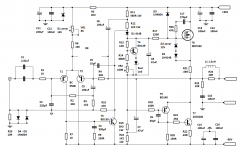
I try to think of some questions - I like this design,
I would give yourself some provision to tame FET oscillations just in case, an R + C in series strung from gate to drain - i.e. if making a pcb put footprints for these parts but you may not need them. In my TGM7 they were my best friends !
What is the purpose of R24 ? - did you intend to have an output inductor in parallel with it ?
Do you want to have space on the layout for a base-stopper for T7 ?
I wonder how it would sound if you adjusted the topology so that T5 and T7 was a CFP instead ? [i.e. move R22 from emitter of T7 and put in the collector, remove R19 and allow option for a base-stopper on T7]
Perhaps try the sound without R8 (I used this trick once but later discarded it), do you need the zener D1
Guillermo,
I like your amp very much. You should build it in the same Bigun has been doing all these years, because you have examined amp topologies here since 2004 and maybe, just maybe, you should build one of your creations. You might even ask Prasi or AlexMM to lay out the pcb!
I will support your build, of course. I'm an old geezer so I don't do much building these days, but I'm pretty quick on the keyboard.......
Ciao,
Hugh
Hugh: thanks you for your words.
"I will support your build, of course". I admire his attitude of always advise.Thank.
"I will support your build, of course". I admire his attitude of always advise.Thank.
Hi all.
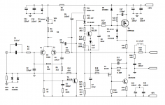
I need to know what the function does T5, is a buffer or phase splitter? It is to determine the value Rc and Re.
Thanks.
I need to know what the function does T5, is a buffer or phase splitter? It is to determine the value Rc and Re.
Thanks.
Hi all.
I need to know what the function does T5, is a buffer or phase splitter? It is to determine the value Rc and Re.
Thanks.
The technical term is common emitter amplifier. The output will be an inverted version of the input signal.
Hi.
T5 is a good idea to be a mosfet?
My inclination would have been to make T5 a bipolar and T7 a mosfet to form a complementary feedback pair and to have given the upper half of the circuit the same treatment.
mjona.
Thanks for your advice. But the idea is just to make the NMOS - BJT quasi output stage. This idea is being developed in the thread "Very simple quasi complimentary MOSFET amplifier" (Ranchu32).
Thanks for your advice. But the idea is just to make the NMOS - BJT quasi output stage. This idea is being developed in the thread "Very simple quasi complimentary MOSFET amplifier" (Ranchu32).
Guillermo,
The best option, in my view, would be to use the nmos on the positive rail and the npn quasi on the negative rail.
Reasons:
1. When you drive the mosfet from the bottom of a bootstrap it is possible to drive the gate just above (no more than about 1V) the positive rail. This brings the source higher towards the positive rail, maximising the efficiency of the output swing.
2. When you drive a quasi device, you have to use a preceding phase inverter to keep the output from the collector in phase with the source output from the upper mosfet. This phase inverter costs some voltage off the negative rail, limiting how close the output can come to the negative rail. If the bias voltage wrt the negative rail is 0.6V, rather than 4V on a mosfet, you pick up some rail efficiency. In fact you lose about 4 volts, almost as good as the bootstrapped n mosfet.
Combining #1 and #2 reasons it is best to use nmos upper and npn quasi lower.
Ciao,
Hugh
- Status
- Not open for further replies.
- Home
- Amplifiers
- Solid State
- No Miller cap, Double bootstrapping amp.