I don't know, if its value is below 1n then it is probably slowing down the amplifier to preserve from oscilations again..GEirin said:
Thank you for the explanation. What is your opinion the C5?
GEirin said:Now, I think other new amplifier. A symmetrical amplifier with double bootstrap? humm.....
darkfenriz said:mirror T1,T2,T3- two complementary dirrirential stages with double bootstrap....may be interesting, don't you think?
😀 Yes, symetrical amplifier with double bootstrap may be very interesting
😀 😀
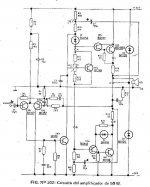
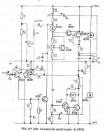
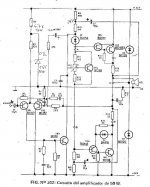
GE50W amplifier
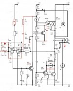
Here first schematic.
I improve my old amplifier. I look many similar amplifier.
Input stage: Yamaha RX795, Ax392 and other Yamaha.
Vas: Arcam A60.
Output stage: Arcam A60, Cyrus 1, Naim.
Other amplifier: DX standart, Leach.
What is your think about the attached schematic?
Thanks
Guillermo.
Here first schematic.
I improve my old amplifier. I look many similar amplifier.
Input stage: Yamaha RX795, Ax392 and other Yamaha.
Vas: Arcam A60.
Output stage: Arcam A60, Cyrus 1, Naim.
Other amplifier: DX standart, Leach.
What is your think about the attached schematic?
Thanks
Guillermo.
Attachments
Try taking C5 from the collector of VAS to the fb node, not to ground.
You may then be able to drop the cap across the fb resistor.
Can't tell you values, you need to find them empirically.
I generally agree with MikeB, who is 1 smart guy.....
Hugh
You may then be able to drop the cap across the fb resistor.
Can't tell you values, you need to find them empirically.
I generally agree with MikeB, who is 1 smart guy.....
Hugh
Rail resistances or two supplies, one for the input (higher voltage) and higher
power to the output... this "sounds"...easy to check and works fine.
Good ideas you are having friends.
Even my Symassym worked better with big rail resistances...to separate (insulate, to turn independent, not affecting one to the other) input supply voltage and output supply voltage....that PSSR people use to worry about...good worries....make sense and sounds.
My supplies, i think they are normal cheap ones.... loose voltage when drained during peaks... the input senses that... audio is modulated ... separating, using double output transformers, or, the worst trick, the use of rail (or rails) resistances to reduce the input voltage (also big condensers to help stabilize) works nice.
Try it folks...do not believe.... it is easy to try...do it and listen.
To the worst method.... the resistance, the unit must drop 3 to 5 volts (minimum)...and then you will listen better quality music.... this is the main reason people do not like the method and do not even try.... they do not know what they are loosing in sonics because of that.
They think...this is bad..will loose voltage swing..so..will not even try and goes living into the ignorance...because have not tasted the cake and go telling tastes bad.
regards,
Carlos
Hi Hugh.
Thank for you reply.
C5 is in feedback.
C6 is colector Vas. This cap not a ground, to the node FB. Ok.
Guillermo
Thank for you reply.
C5 is in feedback.
C6 is colector Vas. This cap not a ground, to the node FB. Ok.
Guillermo
Hi hermano Destroyer.
Thank for you reply.
Yo tengo pensado como opción usar fuentes separadas.
One suply for Vas and output.
Other suply for input stage and preamplifier. (+15V -15V)
Guillermo.
Thank for you reply.
Yo tengo pensado como opción usar fuentes separadas.
One suply for Vas and output.
Other suply for input stage and preamplifier. (+15V -15V)
Guillermo.
Hi all,
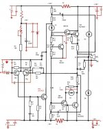
I woud propose these changes to Gulliermo's amplifier, they are showed in the photo.
1. the RC group I have added to schematic reduce the global feedback ratio to around 26 dB. This feedback network is well knowed from stasis amplifiers , but in these amp the global NFB is reduced to zero. In the Gulliermo's amplifier isn't possible reduce to zero the global NFB because it hasn't the many pairs of power bjts in the out like the stasis amplifiers have (or had).
I this moment I forgotten that a similar network is been used in some (or several.......) Nakamichi amplifiers.
I have studied very much the Gulliermo's amplifier and I think this is a very strategic but simple mod.
2. the others change are:
tr7=tr8=mj15003 or mj15023
tr1=tr2=bc557b or bc556b
c2= 47uF 35V or 50V hight speed series bypassed with 22nF 50V cap
c3= 470uF 16V no polar electrolitic bypassed with 22nF 50V cap
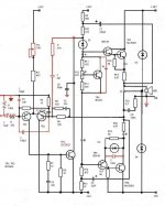
the cap 100nF added near to D2 is good.
the cap added near T4 is OK if it's=10nF.
the cap in the RC group with R=47K should be = 22uF 35/50V
the cap 100pF between the bases of input transistor tr1 and tr2 is bad.
the cap between tr1's base and ground is OK.
the input resistance of 100K is OK
the input resistance of 220 Ohm is OK but It must be 3,9K
the 10k trimmer is bad
the 4,7K resistor near trimmer is bad
- Status
- Not open for further replies.
- Home
- Amplifiers
- Solid State
- No Miller cap, Double bootstrapping amp.