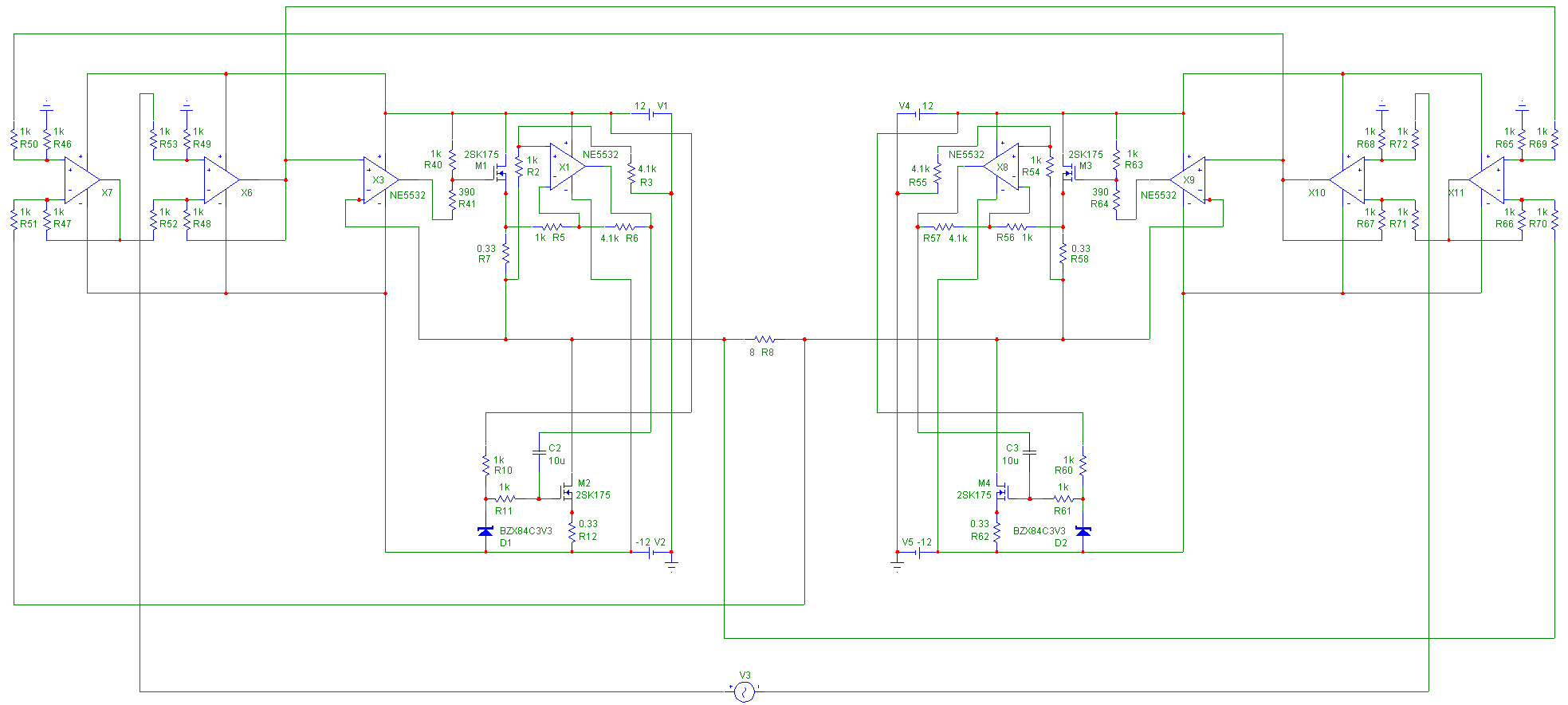
Here the schematic of the simulated circuit.
2 op amps might be avoided and gain is still 1 for simplicity.
2 op amps might be avoided and gain is still 1 for simplicity.
Bernhard
Why don't you try a simple
voltage gain stage (say 26 db)
with discrete components
and feedforward topology?
ciao
Federico
P.S. Have you had your MCap working?
Why don't you try a simple
voltage gain stage (say 26 db)
with discrete components
and feedforward topology?
ciao
Federico
P.S. Have you had your MCap working?
Bernhard,
Keeping the picture of your ciurcuit on your 'own' server bypasses the normal size limits of max 800 pixels wide (your previous one is 1967 pix wide) but that does not improve readability. Maybe some scaling would be helpful. I use a screen resolution of only 1152x864 as a compromise on a 17" screen, I think most of us do not use higher resolutions. A lot of horizontal scrolling is involved.
Another remark is that you use a .jpg for your picture file, which is unfit for line drawings. The previous one is 334kB big. Making it a .gif file reduces this to 76kB and maybe that could have been ven better when the original file was saved as .gif in the first place. Now I converted it. Gif files are lossless (except for colours, 256 colour limitation) and much smaller than .jpg for line drawings.
I use a broadband connection, so for me it is no problem, but I think many people in this forum still use a modem connection.
Steven
File formats for Schematics
PDFs are even smaller and higher quality (vector format), but you can only include them as link.
PDFs are even smaller and higher quality (vector format), but you can only include them as link.
Steven said:Making it a .gif file reduces this to 76kB and maybe that could have been ven better when the original file was saved as .gif in the first place.
Thanks, I will try that.
What about the circuits ?
Bernhard
fscarpa58 said:Bernhard
Why don't you try a simple
voltage gain stage (say 26 db)
with discrete components
and feedforward topology?
ciao
Federico
P.S. Have you had your MCap working?
Evaluation is easier with op amps for me.
Still had no time for...
Bernhard
Benrhard!How are you?How is your amp?I think of you amp!
*Vi+=VBeo+Vbe*sin(omega*t)
ib+=Is*exp[Vi+/UT)
*Vi-=VBeo+Vbe*sin(-omega*t)=VBeo-Vbe*sin(omega*t)
ib-=Is*exp[Vi-/UT]
*furier:
(Vo+) - (Vo-)=2rd 4rd is cancel but 3rd 5rd increase a factor of 2
where VBeo=Vbe bias
*Vi+=VBeo+Vbe*sin(omega*t)
ib+=Is*exp[Vi+/UT)
*Vi-=VBeo+Vbe*sin(-omega*t)=VBeo-Vbe*sin(omega*t)
ib-=Is*exp[Vi-/UT]
*furier:
(Vo+) - (Vo-)=2rd 4rd is cancel but 3rd 5rd increase a factor of 2
where VBeo=Vbe bias
i want to have a amp which i can not regconize its sound or human voice!Bernhard!Can you understand my feeling?
Thanks for keeping my thread alive...
I can't follow that.
My amp plans have a break because I built the DAC first.
But I have new ideas.
If you have time, why don't you just built it, all that I have posted runs ok in the sim.
Bernhard
thanh said:*Vi+=VBeo+Vbe*sin(omega*t)
ib+=Is*exp[Vi+/UT)
*Vi-=VBeo+Vbe*sin(-omega*t)=VBeo-Vbe*sin(omega*t)
ib-=Is*exp[Vi-/UT]
*furier:
(Vo+) - (Vo-)=2rd 4rd is cancel but 3rd 5rd increase a factor of 2
where VBeo=Vbe bias
I can't follow that.
My amp plans have a break because I built the DAC first.
But I have new ideas.
If you have time, why don't you just built it, all that I have posted runs ok in the sim.
Bernhard
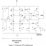
This is my circuit.It is so slow!ORCAD 9.2 is quite stupid.It can't say to me how 2nd and 3rd are.I'm very sad because my amp still has got distortion.I don't like class A but it can give me something.I love feedforward but i don't understand about it much!
Attachments
Bernhard said:Here the schematic of the simulated circuit.
2 op amps might be avoided and gain is still 1 for simplicity.
Any progress?

- Status
- Not open for further replies.
- Home
- Amplifiers
- Solid State
- no mercy distortion killer circuit