Thanks for the update.
About input fets 2sk246/2sj103: I don't remember mentioning the grade (GR; BL; Y).
What is the preferred grade?
About input fets 2sk246/2sj103: I don't remember mentioning the grade (GR; BL; Y).
What is the preferred grade?
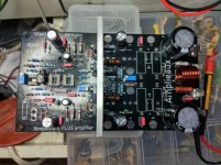
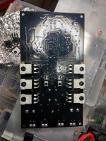
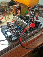
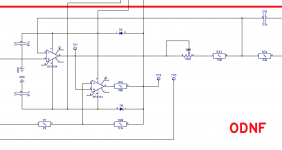
Initial test of the AX3 look good (I haven't heard it yet though). The amp is very stable and looks great on the scope. I've got a second input stage assembled with a high speed ODNF circuit but it's got some bugs to work out, looks like a bad solder joint may have damaged some parts. Next on the list is some higher voltage supply stability testing (running +/- 56V at present) and some proper distortion measurements. My scrap metal heat sink likely won't be up to the task with this many output devices though.
This version is more of a no holds barred style of build with a more complex power supply for the input stage and a new concept of protection schemes, not nearly as simple as the AX2 version. Much more powerful, but hopefully as good sounding (time will tell!)
A monster is on the way!
Good work man! 🙂
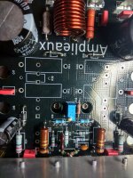
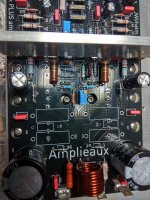
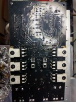
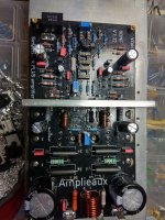
My progress with the baby.
Attachments
-
 IMG_20201027_180818.jpg980.3 KB · Views: 352
 -
 IMG_20201027_192646.jpg618.4 KB · Views: 337
 -
 IMG_20201027_193843.jpg742.7 KB · Views: 339
 -
 IMG_20201027_195029.jpg992.4 KB · Views: 358
 -
 IMG_20201027_195809.jpg742 KB · Views: 326
 -
 IMG_20201027_205956.jpg619.6 KB · Views: 173
 -
 IMG_20201027_211619.jpg756.5 KB · Views: 165
Last edited:
Hi Valery and jwilhelm,Hi Daanve,
Good question )) However, I wouldn't compare those two amplifiers directly.
It's not that one of them is better than the other. AX3 is a different caliber.
AX2 utilizes 2 output pairs, AX3 utilises 6 output pairs. 500W at 4 ohms is not a problem for AX3 😱
So - very much depends on your requirements. More power - more cost.
Jeff can give more info on AX3 testing - it's in his hands right now.
Cheers,
Valery
are you thinking about a lower power version of the new AX3 Amp, similar to the AX2, which uses the new bipolar IPS? This would be interesting for me,
Chris
The output board is basically to parallel output stages. It should be easy enough to scale back to a more normal output power. We'll likely offer it as well when time permits.


Thanks for the update.
About input fets 2sk246/2sj103: I don't remember mentioning the grade (GR; BL; Y).
What is the preferred grade?
???
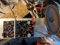
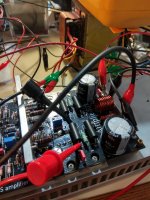
The first test passed without magic smoke
In this first test i use an out of specifications +/-25V. power supply (two regulated power bench power supplies with current limiter. One for the positive and the other for the negative rail).
Now the power supply is +/-37(still a bulb in the primary side and one 22R in series with each rail).
No... smoke again. 🙂
Attachments

Last edited:
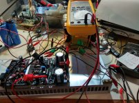
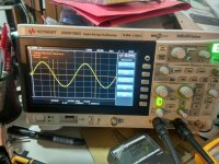
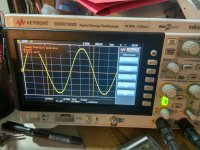
A very first test.
+/-43V
22000uf/Rail
Idle=20mA
Offset=mostly 0V(0-7mV)
Noise=200uV ( 2 meter cheap interconnect cable sorted at the end).
Pout=82W RMS just before clip.
+/-43V
22000uf/Rail
Idle=20mA
Offset=mostly 0V(0-7mV)
Noise=200uV ( 2 meter cheap interconnect cable sorted at the end).
Pout=82W RMS just before clip.
Attachments
-
 IMG_20201029_182655.jpg839.8 KB · Views: 413
 -
 IMG_20201029_182538.jpg885.8 KB · Views: 402
 -
 IMG_20201029_182803.jpg799.4 KB · Views: 393
 -
 IMG_20201029_182917.jpg815 KB · Views: 383
 -
 IMG_20201029_183001.jpg785.7 KB · Views: 391
 -
 IMG_20201029_181542.jpg903.9 KB · Views: 139
 -
 IMG_20201029_183238.jpg791.1 KB · Views: 129
Last edited:
Thimios, did you have a chance to fine-tune the ODNF circuit (using 1KHz sine wave, setting its amplitude at the opamp's output to the minimum)?
2-channel oscilloscope is very useful in this case (you can see both the amplifier output and ODNF output at the same time). You don't need high output swing - some 5-10V RMS is fine.
2-channel oscilloscope is very useful in this case (you can see both the amplifier output and ODNF output at the same time). You don't need high output swing - some 5-10V RMS is fine.
Yes i have done this adjustment,but i can't see a clear sine wave in the test point 1.
I have adjust this for min amplitude.(R26)
I will post a photo when i find time to re scope.
btw,what will happen if we pull two op amp?
Will be the amplifier still functional?
I have adjust this for min amplitude.(R26)
I will post a photo when i find time to re scope.
btw,what will happen if we pull two op amp?
Will be the amplifier still functional?
Last edited:

Yes i have done this adjustment,but i can't see a clear sine wave in the test point 1.
I have adjust this for min amplitude.(R26)
I will post a photo when i find time to re scope.
btw,what will happen if we pull two op amp?
Will be the amplifier still functional?
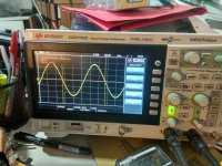
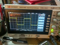
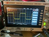
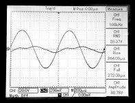
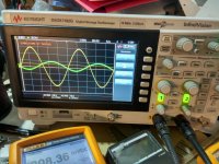
It will not be a clear sine there as that one is the error signal.
Attached is more or less what you will see when ODNF is tuned correctly.
In case you want to pull the pampas out, you also need to ground the VAS load resistor (5.1K). It must be grounded either via the opamp output (virtual ground) or directly to ground. Otherwise the amplifier will show much higher overall gain.
Attachments
Simpelstark
ODNF adjustment.
Output=10V RMS, yellow trace.
Error correction=9mV RMS green trace.
Tp1=9mV at the end of R26 adjustment area.
ODNF adjustment.
Output=10V RMS, yellow trace.
Error correction=9mV RMS green trace.
Tp1=9mV at the end of R26 adjustment area.
Attachments
Last edited:
- Home
- Amplifiers
- Solid State
- No-global-loop amplification