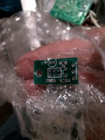
Yes they are. You have an older version of the sensor board that had 10uF electrolytic caps on board.they aren't really needed, the sensors run reliably without the extra caps. You don't need the pull-up resistors either.
Attachments
No R1, R2 not C1 right?
Please what is the code for I2C mini socket?
Thanks. 🙂
Please what is the code for I2C mini socket?
Thanks. 🙂
Attachments
Last edited:
Yes, just a 0.1uF cap and a sensor needed for each. Remember not to get the same sensor for each channel.
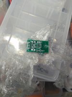
The connecyor on these was just a two row header. https://www.mouser.ca/ProductDetail...nFNwsrLYzJSf7TJG8bNBtTjO8uPYsXlgzieqNgnpbMQ== Mark pin 1 clearly as it's really easy to connect backwards, which didn't hurt anything but stops all I2C communications.
The connecyor on these was just a two row header. https://www.mouser.ca/ProductDetail...nFNwsrLYzJSf7TJG8bNBtTjO8uPYsXlgzieqNgnpbMQ== Mark pin 1 clearly as it's really easy to connect backwards, which didn't hurt anything but stops all I2C communications.
Remember not to get the same sensor for each channel.
What does it mean?
Are different version(I2C adress) available?
What does it mean?
Are different version(I2C adress) available?
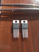
Yes there are eight different addresses available. Each device needs to have a different address so the controller knows what device it's talking to. 579-TC74Ax-5.0VAT Replace the x with a number 0 - 7.
Confirmed, they are different.
I guess that i must edit the source code accordingly.
I guess that i must edit the source code accordingly.
Attachments
Last edited:
Yes you will need to edit the software for all temp sensors or power supplies. You will need to load software called I2C scanner Arduino Playground - I2cScanner. Open the serial monitor and plug in each device one at a time and record each new address that pops up as you go, then enter them in the software. I've attached a build guide for a newer control board that explains it all.
Attachments
Lot of work and questions in the near future. 😉
I hope that you are ready to answer many questions .🙂
I hope that you are ready to answer many questions .🙂
Last edited:
Yes, just a 0.1uF cap and a sensor needed for each. Remember not to get the same sensor for each channel.
The connecyor on these was just a two row header. https://www.mouser.ca/ProductDetail...nFNwsrLYzJSf7TJG8bNBtTjO8uPYsXlgzieqNgnpbMQ== Mark pin 1 clearly as it's really easy to connect backwards, which didn't hurt anything but stops all I2C communications.
I think this will be fine.
Attachments

In summary, this amplifier uses an input and VAS using only local negative feedback BUT an output stage with a unity gain employing negative feedback. The intermediate amplifier receives input from the signal source and inverts a fraction of the output amplifying the sum of both signals. The amplified signal sum drives the output. Therefore, looking backward into the VAS and input stage, there is no global feedback there, but there is for the VAS and the output stage.
The way it works
Hi edbarx,
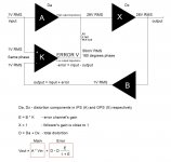
In fact, as the reference signal for ODNF circuit is taken from the input, ODNF is a kind of a global feedback. However, there are 3 things making it pretty special:
1) Error summing point is not at the input stage, but at the VAS output. VAS output is current, forming the voltage in the VAS load resistor. The other side of this resistor is modulated by error signal. This global feedback covers the IPS + VAS, as well as the OPS. It does not change the overall gain though, as it adds 18db and then removes 18db of the total gain (29db + 18db - 18db).
2) The loop gain of ODNF circuit is only 18 db here. This is enough to clean up some garbage and slightly reduce noise, although, those things are low enough even without ODNF in place - that's the requirement for ODNF being efficient.
3) The initial amplifier, before ODNF is applied, is highly linear - THD 1KHz = 0.03%; THD 20KHz = 0.04% - no global loop. It's also wide-bandwidth enough (flat up to 100 KHz). It sounds very good as-is. 18db of ODNF just makes it perfect.
As soon as ODNF is applied, noise (comes down to -117db 20Hz-20KHz), distortion and output impedance go down almost 10 times. Bandwidth increases from 100KHz up to 300KHz. Phase response is very flat and stable within the audio bandwidth. Overall gain is unchanged (29db).
All the rest - you just need to hear. Very cool experience.
Cheers,
Valery
Hi edbarx,
In fact, as the reference signal for ODNF circuit is taken from the input, ODNF is a kind of a global feedback. However, there are 3 things making it pretty special:
1) Error summing point is not at the input stage, but at the VAS output. VAS output is current, forming the voltage in the VAS load resistor. The other side of this resistor is modulated by error signal. This global feedback covers the IPS + VAS, as well as the OPS. It does not change the overall gain though, as it adds 18db and then removes 18db of the total gain (29db + 18db - 18db).
2) The loop gain of ODNF circuit is only 18 db here. This is enough to clean up some garbage and slightly reduce noise, although, those things are low enough even without ODNF in place - that's the requirement for ODNF being efficient.
3) The initial amplifier, before ODNF is applied, is highly linear - THD 1KHz = 0.03%; THD 20KHz = 0.04% - no global loop. It's also wide-bandwidth enough (flat up to 100 KHz). It sounds very good as-is. 18db of ODNF just makes it perfect.
As soon as ODNF is applied, noise (comes down to -117db 20Hz-20KHz), distortion and output impedance go down almost 10 times. Bandwidth increases from 100KHz up to 300KHz. Phase response is very flat and stable within the audio bandwidth. Overall gain is unchanged (29db).
All the rest - you just need to hear. Very cool experience.
Cheers,
Valery
Attachments
AX3 ???
I am about to pull the trigger for some AX2 (V1.32) boards, but... does it make sense to wait for an AX3 version (in development since May) presuming it will be available for DIY?
I am about to pull the trigger for some AX2 (V1.32) boards, but... does it make sense to wait for an AX3 version (in development since May) presuming it will be available for DIY?
Hi Daanve,
Good question )) However, I wouldn't compare those two amplifiers directly.
It's not that one of them is better than the other. AX3 is a different caliber.
AX2 utilizes 2 output pairs, AX3 utilises 6 output pairs. 500W at 4 ohms is not a problem for AX3 😱
So - very much depends on your requirements. More power - more cost.
Jeff can give more info on AX3 testing - it's in his hands right now.
Cheers,
Valery
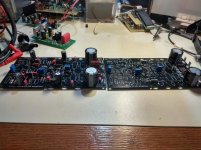
Time to start the second chanel.
Some cool NS Modular front-ends in the background 😉
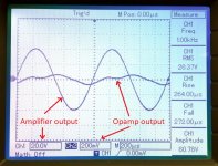
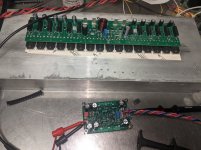
Initial test of the AX3 look good (I haven't heard it yet though). The amp is very stable and looks great on the scope. I've got a second input stage assembled with a high speed ODNF circuit but it's got some bugs to work out, looks like a bad solder joint may have damaged some parts. Next on the list is some higher voltage supply stability testing (running +/- 56V at present) and some proper distortion measurements. My scrap metal heat sink likely won't be up to the task with this many output devices though.
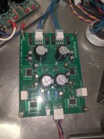
This version is more of a no holds barred style of build with a more complex power supply for the input stage and a new concept of protection schemes, not nearly as simple as the AX2 version. Much more powerful, but hopefully as good sounding (time will tell!)
This version is more of a no holds barred style of build with a more complex power supply for the input stage and a new concept of protection schemes, not nearly as simple as the AX2 version. Much more powerful, but hopefully as good sounding (time will tell!)
Attachments
- Home
- Amplifiers
- Solid State
- No-global-loop amplification