A circuit doesn't 'need' anything, it's all about what you as a designer has as a goal.Jan, I don't want to repeat the argument that we had a few years ago.
But how about a circuit with low open loop distortion? Does it also need large amount of feedback, or smaller amount would suffice? I remember Motorola application note with a power amp schematic using only 10-12 dB NFB - after they introduced their new low distortion power BJTs.
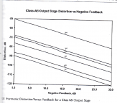
If you look at the Cordell graph I posted before (attached in case you missed it) you see that with a circuit that is quite linear to begin with, you have the freedom to add feedback, and lower distortion, as you like. There's no feedback ratio that increases distortion.
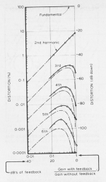
The other example from Peter Baxandall shows a sinmple one-stage FET amp that is not very linear to begin with, and you see that moderate amounts of feedback (say 10dB) actually make matters worse; all harmonics are now larger than without feedback. You have to increase feedback substantially to lower all harmonics (the X-axis runs from right to left here but it should be clear) and eventually you get there..
Jan
Attachments
Last edited:
May be not. Because the local feedback (un-bypassed Rk) @ input tube, producing significantly lower tube gain. Based on that distortion should be lower.And not the best application of feedback. Driver's unbypassed cathode resistor increases Rp and thus increases distortion. But definitely this is an example of a no-NFB pentode amplifier.
Also with smaller -A, dynamic capacitances are smaller too.
But Yes there are 1 full local feedback and 1 partially local feedback at the output tube in this example. But no global feedback. So there are still some FB.
.
But 6072A have relatively higher mju and max input signal p-p of 807 is not large. Baring in mind high output level of digital and other sources. Maybe with the bypassed Rk @ input tube POT always will be close to the minimum value... 🙁
IF we include preamp in chain the outcome will be disaster...
.
Should be checked how many p-p voltage needed for output tube. Then choose input tube to match these requirements and other important parameters like output resistance for driving capabilities etc.
Baring in mind level of the input.
.
Last edited:
Yes, if you use an output transformer, it is very hard to make a reasonable linear amplifier.Well, how should I apply Mr. Putzeys' wisdom in designing my tube amplifiers? Because of output transformer limitations, it is impossible to apply 60 dB feedback, as prescribed.
That's the reason why almost all tube amps show coloration.
Menno Vanderveen has experimented with taking the feedback from the transformer primary.
There you can apply lots of feedback, make the amp very linear, and you just accept the transformer non-linearity.
BTW In his article Bruno mentions that he build a tube amp with 60dB of feedback that sounded very clean, but he gave no details.
PS It is not so much 'Mr. Putzeys' wisdom' as much as solid engineering, of course. You know that.
Jan
But the main issue in SE pentode conn. amplifier will be Output Transformer.
Because of very high internal resistance of tube in that mode of connection.
Much much higher than same tube in triode mode...
Mucho [Hy] in primary 🙂 close to impossible to achieve for just decent LF response 🙁
Because of very high internal resistance of tube in that mode of connection.
Much much higher than same tube in triode mode...
Mucho [Hy] in primary 🙂 close to impossible to achieve for just decent LF response 🙁
Bruce Hofer of Audio Precision designed a circuit that compensates for the ohmic resistance in the primary of the transformer, making the transformer distortion extremely low.
AP analog generators have an output transformer and routinely hit -130dB distortion.
There's an application on the Lundahl website as well.
For some reason, this has escaped the attention of the entire tube amp maffia. 😎
Jan
AP analog generators have an output transformer and routinely hit -130dB distortion.
There's an application on the Lundahl website as well.
For some reason, this has escaped the attention of the entire tube amp maffia. 😎
Jan

In America it's political season, and everything goes batshit. Such is life for a few more days. Some random comments:
Any moving diaphragm generates distortion by time modulating any signal component with every other signal component. Cannot be fixed, only mitigated. Smaller radiating areas have inherently higher distortion of this kind because required excursions must be larger for the same SPL.
The Black model of negative feedback is a simplified version, where the forward pass amplifier is sometimes assumed to include distortions and sometimes assumed to be distortion free. B. Putzeys' model is more complete, and he references P. Baxandall's work back in the '60s (IIRC). None of that means that there's anything wrong, dirty, or somehow ungodly about feedback. It's the only thing that keeps any dynamic system, including life, the universe, and everything, stable-ish through time. Religious stances here are misguided, but common.
Output transformer (OPT) frequency magnitude response errors and distortions scale linearly with impedance at the output valve anode - OPT junction. Less is more better.
All good fortune,
Chris
Actually, that example reduces total distortion at all feedback ratios too. The circuit has 10% 2HD open loop, with negligible higher order distortion. Applying a few dB of feedback reduces 2HD but ADDS 3HD and above. The higher order products eventually peak, and with enough feedback eventually everything falls monotonically like in the Cordell example. If you think about the mechanisms involved it makes sense - You feed back a signal with 2HD added, and the 2HD itself is distorted again and produces mixing products with the original. The overall level gets reduced, but there is now more products in the spectrum. It’s now all these extra products that weren’t there at all before feedback that are objectionable. They are more audible than the original higher level of 2HD. If the amp/circuit is more linear to begin with, there isn’t as much “distorted distortion” produced by the feedback so it’s not bothersome. Or at least not as bothersome.The other example from Peter Baxandall shows a sinmple one-stage FET amp that is not very linear to begin with, and you see that moderate amounts of feedback (say 10dB) actually make matters worse; all harmonics are now larger than without feedback. You have to increase feedback substantially to lower all harmonics (the X-axis runs from right to left here but it should be clear) and eventually you get there..
Yes, that is why taking the feedback from the primary of the OPT, which reduces the driving impedance to very low values, has such a beneficial effect.Output transformer (OPT) frequency magnitude response errors and distortions scale linearly with impedance at the output valve anode - OPT junction. Less is more better.
All good fortune,
Chris
Jan
One example to consider:
A Negative Feedback signal sample is taken from the output output transformer secondary, and fed to an early stage.
So far so good, if all is done well (some say no, some say yes).
Let us discuss the "yes":
. . . Suppose a push pull output transformer is subjected to . . .
Either badly unbalanced quiescent DC,
Or a very large, very low frequency signal.
As a result, the laminations are in Saturation.
Now . . . the negative feedback signal causes the output stage to drive even more current into the output transformer . . .
Oh no, . . . it Increases the saturation.
That makes the problem worse.
Then, think through that scenario again, but with the negative feedback signal sample being taken from the output transformer primary.
Still a problem if the laminations are in Saturation?
Question:
What happens to the IMD of mid frequency and high frequency music tones, when the core is in saturation?
Just asking.
The current bench toy is a 6SF5GT driving a 7591 pentode mode into a 5k SE opt with about 20 dB of feedback from the secondary. With this amp a low distortion first stage error amp is critical and very audible. The input - CCS loaded driving the output stage's 1M grid resistor - currently achieves full power output at about 0.1% thd. I suspect much of feedback's bad rep in the tube world stems from early commercial designs that used high gain 12ax7's with small plate loads or stanky input tubes like the 7199 and relied on loop feedback as a panacea to 'fix it in the mix'.
The previous bench toy was an open loop 6E5P/2A3 combo using the same transformer. With real world music on real world speakers it didn't come close for these ears.
The previous bench toy was an open loop 6E5P/2A3 combo using the same transformer. With real world music on real world speakers it didn't come close for these ears.
That makes the overall amp less sensitive to what is intrinsically happening in the transformer. If you see a FR plot of a transformer that is “too good to be true”, it is often because it was tested driven from a pure voltage source (ie, SS amp). Taking feedback at the plate before the trafo has similar effect, but you can never get that driving point impedance down to zero (you settle for in between). It does tend to reduce distortion mechanisms and FR errors having to do with transformer impedance. And it does that without incurring the actual phase shift thru the trafo which eats into phase margin.
Well, yes, you can always come up with examples of incompetent design. So?One example to consider:
A Negative Feedback signal sample is taken from the output output transformer secondary, and fed to an early stage.
So far so good, if all is done well (some say no, some say yes).
Let us discuss the "yes":
. . . Suppose a push pull output transformer is subjected to . . .
Either badly unbalanced quiescent DC,
Or a very large, very low frequency signal.
As a result, the laminations are in Saturation.
Now . . . the negative feedback signal causes the output stage to drive even more current into the output transformer . . .
Oh no, . . . it Increases the saturation.
That makes the problem worse.
Jan
Jan.didden,
Some people still think that negative feedback fixes everything, including most/all output transformer limitations.
When that does not come true . . .
Call it a incompetent design.
Call it lack of knowledge.
Or call it whatever you want to.
Driving on snow and ice, you come around a corner. If you start to slide and undershoot the turn . . .
do not attempt to continue making the turn. Instead, turn into the direction you are sliding.
Over correction to make the turn will continue the slide.
Turning into the slide will restore control. After that, you can start turning again.
Sooner or later, you are going to experience lamination saturation on over 95% of vacuum tube amplifiers that have output transformers.
Just put on the definitive 1812 Overture recording, done by Telarc. The real canon on that recording had a giant 6Hz signal, turn it up and saturate your laminations.
That problem is not due to incompetent amplifier design. It is due to operator error, Right?
Or, turn into the slide (turn the volume down).
Just my opinion.
rdf,
One good example of synergy is the Fisher 500C / 800C.
It had pretty good sound. Arguable point.
A 12AX7, 7591 push pull, and a very very good output transformer that was capable of working well with beam power operation of high rp output tubes.
The "Wimpy" 12AX7 you mentioned, and a moderate amount of negative feedback taken from the output transformer secondary actually did very well.
Last edited:
Yes, probably there are some people that think that.Jan.didden,
Some people still think that negative feedback fixes everything, including most/all output transformer limitations.
But feedback is a tool, and as any tool, has to be used wise and intelligently.
It certainly doesn't fix everything.
Some problems like output transformers can't easily be fixed, so you live with the problems or buy enormous expensive units.
Nothing new under the sun.
What doesn't help us is accepting the engineering but then saying - I still think it's wrong.
That's religion, not audio engineering.
Jan
It is two-way. Cathode degeneration reduces distortion, but lower Rl:Rp ratio makes steeper load line, which increases distortion. Provided that gain drops with unbypassed cathode, the balance of gain vs. distortion is better for bypassed cathode (or fixed bias with no Rk).Un-bypassed cathode resistor generate local NFB and decrease distortion, not increase.
Not really: https://www.stereophile.com/content/fisher-500-c-vintage-stereo-receiver-measurementsFisher 500C / 800C....actually did very well.
Even my SE bench amp handily exceeds this performance in square wave response, frequency response into speaker loads and THD level/spectra at 2 watts. Since LTSpice was open here are the quick results of an analysis of the Fisher's input stage comparing resistor and CCS plate loads.
| | Fisher 500-C input 12ax7a | |
| | | |
| | R load | CCS load |
Harmonic | Freq [Hz] | % | % |
1 | 1000 | 100% | 100% |
2 | 2000 | 0.646100% | 0.023350% |
3 | 3000 | 0.019440% | 0.000382% |
4 | 4000 | 0.001075% | 0.000007% |
5 | 5000 | 0.000055% | 0.000000% |
6 | 6000 | 0.000005% | 0.000000% |
7 | 7000 | 0.000003% | 0.000000% |
8 | 8000 | 0.000002% | 0.000000% |
9 | 9000 | 0.000002% | 0.000000% |
THD | | 0.646439% | 0.023356% |
| | | |
as I said, no laws prevent a small driver to be linear. it is just a harder engineering task.No matter how well a compression-style bass driver is designed, it has a non-linearity of suspension: spring force is different at different deflection points of its long stroke. A bass driver with large radiating area (1 m2) will efficiently radiate at almost zero excursion, making suspension non-linearity much less important.
efficiency is not related to the wavelength to driver size ratioA radiator of a small size comparative to wavelength has one serious disadvantage: inefficiency. Low efficiency must be compensated by increasing driving power, so driver's design is encumbered by the necessity to handle that power, e.g. mechanical strength, heat dissipation, VC modulation of gap' s magnetic field.
the challenge is that high VC current can drive parts of the steel out saturation and that is very nonlinear.I agree that countermodulation coil may be not very effective. Its effectiveness assumes magnetic coupling with VC, which may not be good under different circumstances. Actually, I am not using countermodulation coils in my Magnavox drivers because I run FCs close to magnetic saturation, at which point the coupling between CMC and VC should be almost completely lost. But position-independent (and lowest) Le is achieved because close to magnetic saturation of the pole piece its permeability gets close to unity and VC behaves like an air core inductor.
most so called open loop distortion reductions are in fact caused by feedback. If we can do now 80dB feedback around a class D amp then it should be possible with tubes as wellMr. Putzeys may be right here, but I believe that if NFB can be avoided, it should be avoided. I believe the effort should be spent on reducing open loop distortion rather than overcoming complications of applying deep global NFB.
sounds like you mean Doppler distortion. Maybe you will find these sound bites interesting:Any moving diaphragm generates distortion by time modulating any signal component with every other signal component. Cannot be fixed, only mitigated. Smaller radiating areas have inherently higher distortion of this kind because required excursions must be larger for the same SPL.
https://purifi-audio.com/2019/12/07/amfm/
YES! 9am Sunday morning here, just read post #285, opened Lundahl's note on "Mixed feedback drive circuits for audio output transformers" made my coffee, started reading and started thinking! And thanks for the opportunity to achieve guru status, Jan - much appreciated but I know it's beyond me!So, all you would-be guru's, have you already started to study the hint in post # 285?
Jan
Attachments
- Home
- Amplifiers
- Tubes / Valves
- No-feedback pentode amplifier