As the title states, when I first power up the amp the output (Left and Right) are quite distorted, almost sounds blown. the issue is amplified if both outputs (A and B) are off and only using headphones.
If I leave it warm up for 10-15 minutes the issue goes away.
I can fix most things (when not working) but this case has me stumped.
I checked the main power I'm getting +/- 76VDC. I scoped it and there is a good 80mV ripple. I'm not sure that'll cause it as even when once warmed up the ripple is still there but the amp sounds fine.
I can't find the service manual for this amp, but am using the Alpha 400 service manual for reference as they are very close to the same amp. small component differences but the same circuits that I can tell.
I've adjusted the Zero Balance and the Idle Current Adjustment. They were both out of spec to the 440 manual. With no output sitting there the left channel was getting quite warm but that isn't the case anymore.
So my question is, how do I go about troubleshooting this problem? I know I'll have to setup when cold do some testing stop reset and repeat once cooled down... But I am hoping someone can give me some suggestions on how to start.
Tools I have are;
- 2 x 800w 8Ohm Dead loads
- 4 ch 50mhz Digital Scope
- Single output Frequency Generator
- handful of Fluke/Non-Fluke Meters.
So there's nearly nothing I can't do. but again. slightly stumped here. I'm usually fixing dead channels and blown power supplies.
Any suggestions on going about this is appreciated.
Vin
Last edited:
I already have that manual, it's what I've been using to date, circuit is near the same, but the transformer output and DC regulation is slightly different (440 = +/-73VDC rails, 450 = +/-76VDC Rails)
so some of the components differ, like the power caps in a 440 are 80V caps, where the 450 are 100V caps. but the same physical size and Farrad rating.
Tracing part of the power supply is where I realized the circuit and design is roughly the same.
But what I'm looking for is someone experience to give me a better idea on troubleshooting this issue.
Vin
It's clearly associated with the warm-up period but that could also mean the electrolytics are ageing. Does it appear to have original electrolytic caps still fitted or have some been replaced already? Otherwise, at > 35 years old, you'd have to suspect caps as failing on any domestic amplifier product.
If warming up (without anything actually playing) is all that it takes, yes, bad caps are clearly a possibility. (I had to take a hairdryer to my PC lately to get it to cold boot again, and that's not even 9 years old. Sure enough, there's a bulging cap staring at me on the board.) A bad power switch would be another classic.
If it takes some music playback, bad contact in the protection relay or speaker selector is another common issue.
If it takes some music playback, bad contact in the protection relay or speaker selector is another common issue.
Correct, I just need to turn it on and leave it 10-15min (pre-amp is still off) and when I go to use it after that time there are no issues at all.
All the caps appear original. Only thing I see out of place is the main fuse rated at 12 amps but a 10 amp fuse sits in it's place. The owner I bought it from told me about the fuse and said it happened 10 years ago when he improperly hooked it up. Not sure what that meant or how. But he was the original owner from 83/84.
The 4 main power caps appear to have leaked a little but everything else appears to look fine, I don't see any other leaked or bulging caps. Nothing like other amps I've had to fix.
The DC ripple that's present doesn't change when cold or warm. So I'll look at re-caping the Main Amp and Power Amp boards first and eventually work my way to the power supply regulation. Tight on funds atm.
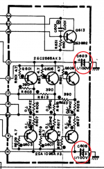
I do have a question, I've attached a pic of the power amp schematic. What would the purpose of the circled 1uf/100v cap between the collector and ground there? Filtering to ground?
Vin
All the caps appear original. Only thing I see out of place is the main fuse rated at 12 amps but a 10 amp fuse sits in it's place. The owner I bought it from told me about the fuse and said it happened 10 years ago when he improperly hooked it up. Not sure what that meant or how. But he was the original owner from 83/84.
The 4 main power caps appear to have leaked a little but everything else appears to look fine, I don't see any other leaked or bulging caps. Nothing like other amps I've had to fix.
The DC ripple that's present doesn't change when cold or warm. So I'll look at re-caping the Main Amp and Power Amp boards first and eventually work my way to the power supply regulation. Tight on funds atm.
I do have a question, I've attached a pic of the power amp schematic. What would the purpose of the circled 1uf/100v cap between the collector and ground there? Filtering to ground?
Vin
Attachments
Yes, commonly called decoupling or bypass caps, fitted locally to ensure a low impedance path.
Since all the electrolytics are original as you found, you know what comes next.....😉 Have fun and you don't need to buy the most wonderful brand high priced caps. Just any working caps will be better than what you have but pick a reputable manufacturer like Panasonic, Nichicon, Rubycon, United Chemicon, Elna. Epcos etc. and select popular audio grades with a decent working life of more than 2000 hours. Note that size is now just a fraction of those from 35 years ago.
Since all the electrolytics are original as you found, you know what comes next.....😉 Have fun and you don't need to buy the most wonderful brand high priced caps. Just any working caps will be better than what you have but pick a reputable manufacturer like Panasonic, Nichicon, Rubycon, United Chemicon, Elna. Epcos etc. and select popular audio grades with a decent working life of more than 2000 hours. Note that size is now just a fraction of those from 35 years ago.
Check for cracked solder joints around the PSU area, especially around big resistors and transistors. Bad caps in Japanese amplifiers are extremely uncommon and replacing these will almost certainly not solve your problem.
I think it may be Bias Problem, Check the Voltage across the Power Resistors (5Watt resistors on Power Transistor PCB) First Measure the voltage across those resistors when you start up & then again measure the voltage when it gets warm up and the sound is fine. This voltage should be in mili-volt. Note both the readings, if there is a difference then you may need to adjust the Bias accordingly.
I think it may be Bias Problem, Check the Voltage across the Power Resistors (5Watt resistors on Power Transistor PCB) First Measure the voltage across those resistors when you start up & then again measure the voltage when it gets warm up and the sound is fine. This voltage should be in mili-volt. Note both the readings, if there is a difference then you may need to adjust the Bias accordingly.
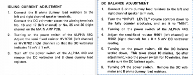
There isn't a dedicated Bias per-say on this amp. There is only a DC balance and Idle Current adjustment.
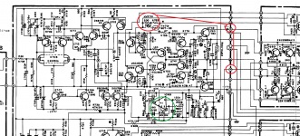
I've attached the procedure for the Alpha 440 and a snipit of the power amp section with potentiometers highlighted.
The OpAmp (IC901) is an NEC uPC741C and I understand that this OpAmp provides a variable bias, and if I understand the 440 manual properly at low power draw the amp operates in a Class A, and when the power requirement is at a higher point the amp switches to Class AB (B) as the manual describes it.
The more I look at the circuit, this opamp could be the root cause, or the feedback to it is unstable on startup.
Love the help guys. Thank you
Vin
Attachments
IC901 looks to the DC servo, tries to keep the output at 0VDC no matter what. That won't or shouldn't affect the idle current if it's working correctly.
Craig
Craig
IC901 looks to the DC servo, tries to keep the output at 0VDC no matter what. That won't or shouldn't affect the idle current if it's working correctly.
Craig
ah, I see. I was reading it as a 'Balance" is also a bias center. I found it ironic that the 10 min warm up time depicted in the manual was also about the amount of time I need the unit powered up that clears up the issue I'm having.
I've been using it and working too much so I haven't had time to open her up for more looks. this weekend hopefully.
Vin
- Status
- Not open for further replies.
- Home
- Amplifiers
- Solid State
- Nikko Alpha 450 - dirty/distorted sound until warmed up.