Then build your own soft start with an AC output to suit the protection circuit.
I would expect 12V relays to work with 12Vac giving ~15Vdc to 18Vdc that you can regulate down to 12V to suit the relays.
If you go for 24V relays then you need a higher transformer voltage to suit.
example multipurpose transformer 6-0-6Vac 6VA has a maximum continuous AC current of 500mA.
After rectifying and smoothing (capacitor input filter)you are left with a maximum continuous DC current of ~250mAdc.
If you use less than 50% of that the transformer will run cooler and have good reliability.
That leaves with with a continuous ~125mAdc to power all your auxiliaries.
The 12V relays should operate on less than 20mA each, some will be much less (typical maximum coil resistance is ~1100ohms)
Last edited:
That's a great idea 🙂, but I don't think I have the skills for that just yet. I would like if I could use the materials I already got. Maby I would be better off not having the speaker protection board.
keep the speaker prot.
It is useful for isolating the speaker when excess DC is detected.
It also can be used to delay the speaker connecting while the amp starts up and sometimes sends spurious pulses/DC to the output
It can also switch off the speaker immediately the amp loses mains AC. That stops weird noises affecting the speaker if some other component sends spurious signals when shutting down.
You could get a small 12V AC transformer for the speaker protection board. This will make things really easy with no ground loops or complicated wiring.
Okay I'll keep it and figure out a solution. There is these small PCB transformers faily cheap in my region: http://tinyurl.com/jh6h8oo
Then I will be able to power the Speaker Prot. on its own tranformer.
Then I will be able to power the Speaker Prot. on its own tranformer.
I was looking at the Audio Component Grounding and Interconnection by David Davenport here on diyaudio and I saw the circuit breaker panel.
I found this on a danish site: TE Connectivity PS0S0DSXB=C1265 250 V/AC 10 A
Could I use this successfully in my amplifier as a circuit breaker unit?
I was also wondering what current the fuse should be rated at?
I have also made an updated diagram for my setup:
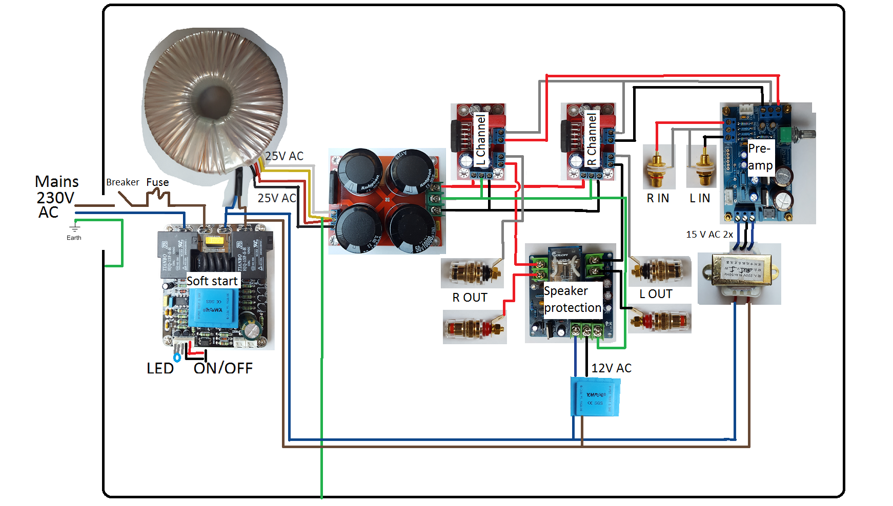
I hope you can see if there is any flaws.
I found this on a danish site: TE Connectivity PS0S0DSXB=C1265 250 V/AC 10 A
Could I use this successfully in my amplifier as a circuit breaker unit?
I was also wondering what current the fuse should be rated at?
I have also made an updated diagram for my setup:
I hope you can see if there is any flaws.
Run the audio from preamp as a left pair and a separate right pair. Not as a triplet into two pairs.
Similarly run the audio from input sockets as separate left and right pairs to the pre-amp.
Finally the speaker outputs from the amplifier run as pair for each channel.
To the prot PCB and then from the prot pcb to terminals.
Run every inter module connection as pairs, except where the dual polarity PSU needs a triplet.
These pairs can be close coupled, or twisted, or coaxial. Never widely separated.
The prot PCB probably does not need an Earth. The single polarity supply can be isolated from all other supplies. The timer/detector and relays all operate from the isolated supply. The audio inputs and the relay output/s are the speaker pairs.
Last edited:
That iec socket is a medical version thatdoes not use the Y rated capacitors.
Use the ordinary version that has both X rated caps and Y rated caps for better filtering of RF.
10A is far too high. Look at using 1A for a small power amplifier, or 3A, or 6A, for a very big power amplifier.
Use the ordinary version that has both X rated caps and Y rated caps for better filtering of RF.
10A is far too high. Look at using 1A for a small power amplifier, or 3A, or 6A, for a very big power amplifier.
AndrewT thanks for the great reply. I will definetly follow your suggestions.
I will be looking for a different IEC socket with a 1-6 A fuse.
I will be looking for a different IEC socket with a 1-6 A fuse.
I have 1 m of this shielded cable I think I want to use in the signal between input, pre-amp, power-amp and output. It is this cable:
16 AWG stranded (19x29) TC conductors, polyethylene insulation, twisted pair, overall Beldfoil® shield
(100% coverage), 18 AWG stranded TC drain wire, PVC jacket.
I think the shield is to be wired to the chassis/ground, but I am not shure. Can someone tell me this because I was trying to read the Audio Component Grounding and Interconnection - David Davenport but I don't quite understand it.
I think 1 m is too little so I also have some UL 2547 PVC shielded 28 AWG cable, but is this cable any good in terms of transport of signal quality?
Maby I could use the 18 AWG as power cables and the 28 AWG as signal cables?
I also found some 1,6A and 3,2A slow fuses and I pulled this IEC socket from a LCD TV that I think I can use:

Can somebody tell me if this is a good idea? I can't see what the board does exactly other than offer a neat ground connection and on/off main swich.
16 AWG stranded (19x29) TC conductors, polyethylene insulation, twisted pair, overall Beldfoil® shield
(100% coverage), 18 AWG stranded TC drain wire, PVC jacket.
I think the shield is to be wired to the chassis/ground, but I am not shure. Can someone tell me this because I was trying to read the Audio Component Grounding and Interconnection - David Davenport but I don't quite understand it.
I think 1 m is too little so I also have some UL 2547 PVC shielded 28 AWG cable, but is this cable any good in terms of transport of signal quality?
Maby I could use the 18 AWG as power cables and the 28 AWG as signal cables?
I also found some 1,6A and 3,2A slow fuses and I pulled this IEC socket from a LCD TV that I think I can use:
Can somebody tell me if this is a good idea? I can't see what the board does exactly other than offer a neat ground connection and on/off main swich.
An exposed mains filter will spray emi onto any nearby circuits.
The mains filter needs to be inside a shielding can (Faraday cage) that is electrically connected to the circuit enclosure by a ultra low impedance connection.
If any mains cable is exposed from the enclosure entry to the shielding can of the mains filter, then that too needs to be shielded to prevent spraying of emi from the cable.
Thanks you 🙂 I will use this one in stead:
With a 3 A rating.
What about my other questions about cables?
An externally hosted image should be here but it was not working when we last tested it.
With a 3 A rating.
What about my other questions about cables?
Last edited:
Update
I have wired all the connections except from the net filter to the soft start board and the transformers. And a fuse.
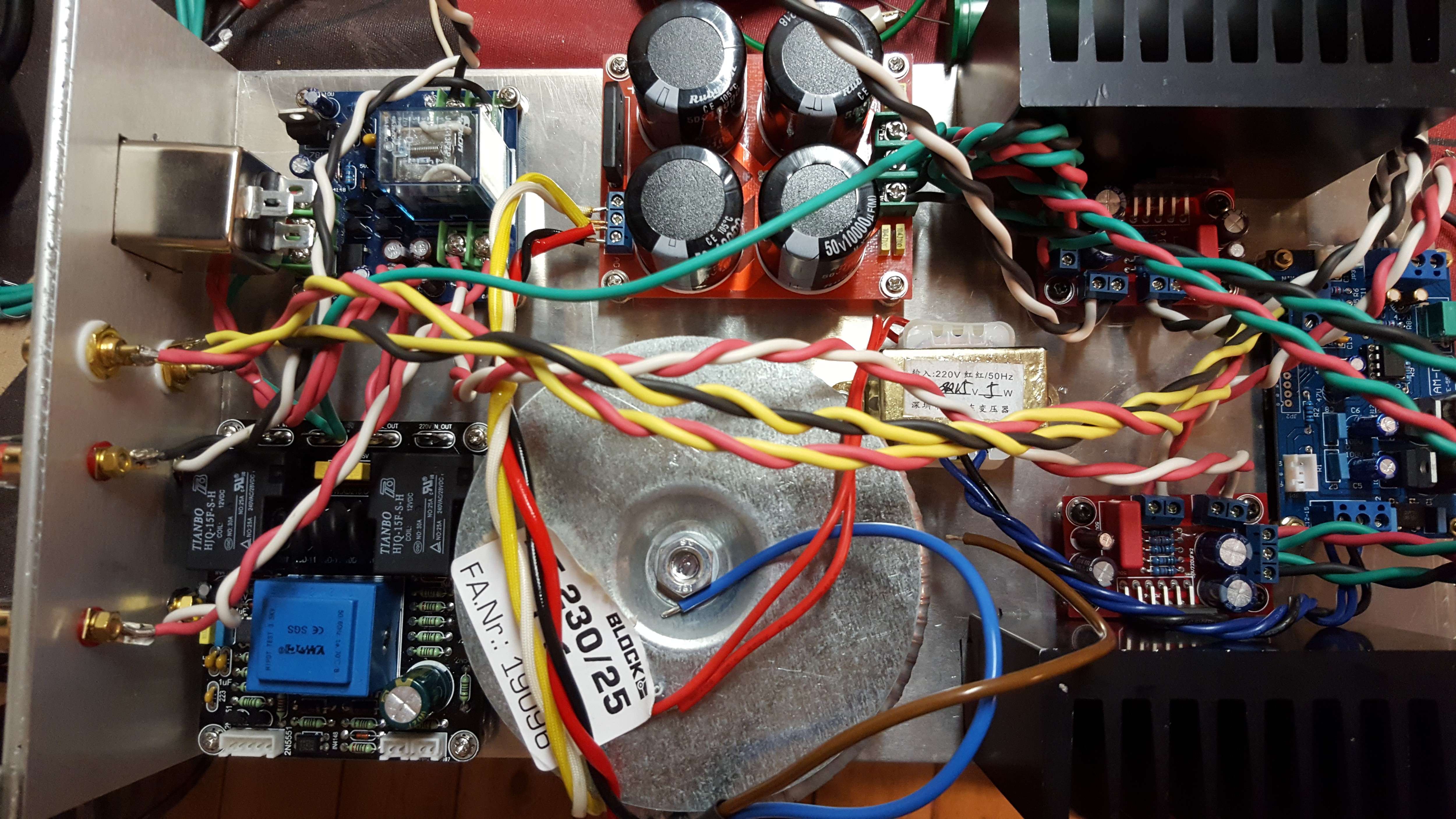
I made the frame of a trick scrap aluminium board.
So diyAudio do you see any errors or have you any improvements for the design? Any help is appriciated.
I have made the lamp test thing that I will be using in the test phase.
I can take more pictures if nessesary.
I have wired all the connections except from the net filter to the soft start board and the transformers. And a fuse.
I made the frame of a trick scrap aluminium board.
So diyAudio do you see any errors or have you any improvements for the design? Any help is appriciated.
I have made the lamp test thing that I will be using in the test phase.
I can take more pictures if nessesary.
Connect a green/yellow fairly short insulated stranded wire from IEC socket "earth" to Chassis. This is your Protective Erath (PE). Either to the back panel, or to the floor. Make the connection permanent and mechanical.
I can see screws holding the IEC to the chassis. Use longer bolts and add a nut on the inside. The PE wire can be bolted under this nut if you use appropriate washer/s
Do not remove it for any reason.
When you are ready to make another connection to Chassis use a different bolt/location.
I can see screws holding the IEC to the chassis. Use longer bolts and add a nut on the inside. The PE wire can be bolted under this nut if you use appropriate washer/s
Do not remove it for any reason.
When you are ready to make another connection to Chassis use a different bolt/location.
UPDATE
Hi all🙂
I've connected the ground as you said AndrewT.
Now I've started testing. I'm having trouble with the Soft Start Board.
When I turn the power on (with the light bulb tester) the small diode glows red and no light in the bulb, OK.
Then when I push the ON switch (momentary switch) it turns green shortwhile and back to red, meanwhile a flash from the bulb appears. Now when I measure the voltages I get about 20V AC on the soft stard OUT terminal (It says 220V so I know it is wrong)
So I tried to wire directly from the fuse and IEC socket to the transformer to see if something was wrong with the transformer. When I switch the bulb tester on it lights up and slowly fades away. I measured about 22V AC on the secondary leads and 55V DC after the bridge rectifier. This is a bit too high for me, and too high according to Decibel Dungeon, I should be getting 31-35 V DC. I think I will rebuild the bridge rectifier.
This makes me think that the transformer is OK.
So something is wrong whith the Soft Start Board, I think.
I am running a speaker protection board from thel 12V AC transformer on the Speaker Protection Board. This switches on as expected.
I have not connected the termoswitches that came with the Speaker Protection Board, since one of them is faulty.
What do you think?
Okay now I have a new idea 🙂
I just disconnected the leads to the power amplifiers (I should have done this in the beguinning) and now the Soft Start Board works just fine and ligts red then green when switched on. The light bulb in the tester does not come on visibly.
I am guessing that since I have the Speaker Protection Board powered from the Soft Stard Board, it draw too much power and the Soft Start Board didn't funktion correctly.
My current problem is that i get 60 V DC from the bridge rectifier.
Hi all🙂
I've connected the ground as you said AndrewT.
Now I've started testing. I'm having trouble with the Soft Start Board.
When I turn the power on (with the light bulb tester) the small diode glows red and no light in the bulb, OK.
Then when I push the ON switch (momentary switch) it turns green shortwhile and back to red, meanwhile a flash from the bulb appears. Now when I measure the voltages I get about 20V AC on the soft stard OUT terminal (It says 220V so I know it is wrong)
So I tried to wire directly from the fuse and IEC socket to the transformer to see if something was wrong with the transformer. When I switch the bulb tester on it lights up and slowly fades away. I measured about 22V AC on the secondary leads and 55V DC after the bridge rectifier. This is a bit too high for me, and too high according to Decibel Dungeon, I should be getting 31-35 V DC. I think I will rebuild the bridge rectifier.
This makes me think that the transformer is OK.
So something is wrong whith the Soft Start Board, I think.
I am running a speaker protection board from thel 12V AC transformer on the Speaker Protection Board. This switches on as expected.
I have not connected the termoswitches that came with the Speaker Protection Board, since one of them is faulty.
What do you think?
Well, first I think the chassis is too small for all those boards and for the same reason you have the input too close to transformers and the wires from input are not shielded to prevent any EMI... and you are right about the voltage after rectifier...if you have 22 vac at the secondary you should have around 31vdc after rectifier board (22X1.4=30.8)... I am guessing here that you made a mistake with wiring the secondaries to rectifier board. make sure you measure well the voltages and connect the right ones to the board...is that a dual mono supply?...By the way did you put a "pilot light" to see if amp is on or off? some switches come with lights already.
Last edited:
Yes, I know it is too small. It's hard to maneuver around. Right now I need to get it playing.
I don't have a pilot light, how can I make one? Connect the speakers? A led diode?
On the transformer it says:
Pri.: blue-brown 230V-1.1A 0
Sec.: black-red 25V-4.60A 5AT
yellow-white 25V-4.60A 5AT
I only have a single bridge rectifier, so I wired it:
25V White
GND Yellow-Red
25V Black
How should it be?
Edit: I just tried yellow/white-red/black. It showed 60V DC.
Last edited:
- Status
- Not open for further replies.
- Home
- Amplifiers
- Chip Amps
- Newbie's first post: A LM3886 project from a few years ago