Hello diyaudio! ")
I need to know if I'm on the right track!
This is my story:
I A few years ago I decided I wanted to build my own amplifier. So I starded buying peaces off Ebay. I wanted to build a stereo amplifier for my monitor speakers for my PC. I bougt a kit of LM3886 chip boards and a power supply board:
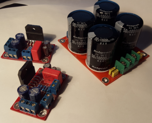
I thought it looked pretty decent.
So I went shopping for other things:
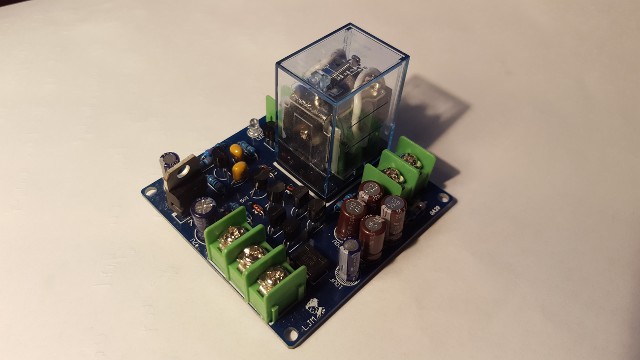
Speaker protection board (Stereo. AC 15V):
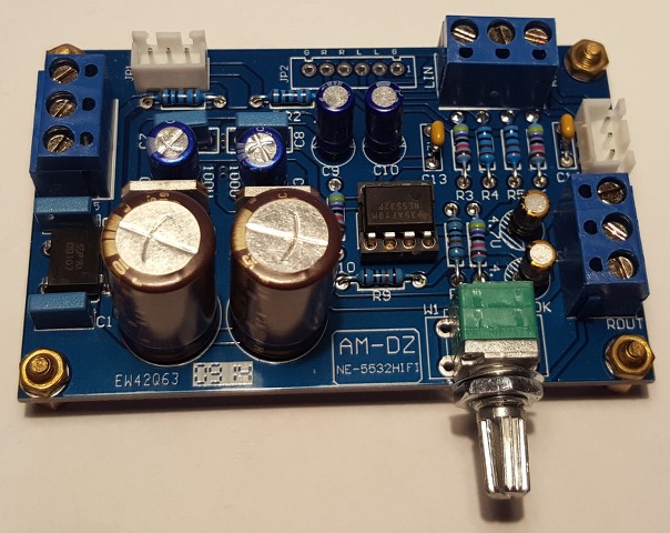
Preamplifier (NE5532):
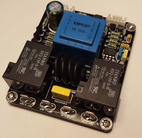
Soft start board (Like this:Ebay link) :
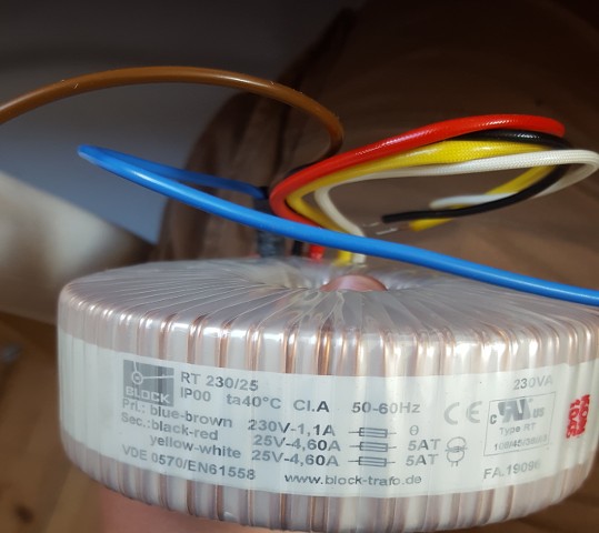
And finally the transformer (230V,2x25V,230VA):
(I still need to sort out the ground wires and add a fuse)
Please can anyone tell me if it's an all right setup or it is a weired combination.
Any thoughts of improvements is appriciated.
Is the whole soft start/speaker protection too much?
Should I use two rectifier bridges instead?
Thanks!
I need to know if I'm on the right track!
This is my story:
I A few years ago I decided I wanted to build my own amplifier. So I starded buying peaces off Ebay. I wanted to build a stereo amplifier for my monitor speakers for my PC. I bougt a kit of LM3886 chip boards and a power supply board:
I thought it looked pretty decent.
So I went shopping for other things:
Speaker protection board (Stereo. AC 15V):
Preamplifier (NE5532):
Soft start board (Like this:Ebay link) :
And finally the transformer (230V,2x25V,230VA):
(I still need to sort out the ground wires and add a fuse)
Please can anyone tell me if it's an all right setup or it is a weired combination.
Any thoughts of improvements is appriciated.
Is the whole soft start/speaker protection too much?
Should I use two rectifier bridges instead?
Thanks!
Last edited:
read
Audio Component Grounding and Interconnection - diyAudio
and Bonsai's amp wiring article/pdf
read
What is Gain Structure? - diyAudio
and decide whether you really need a pre-amplifier with gain.
Audio Component Grounding and Interconnection - diyAudio
and Bonsai's amp wiring article/pdf
read
What is Gain Structure? - diyAudio
and decide whether you really need a pre-amplifier with gain.
Hi Andrew,
-Chris
What does that have to do with anything? Certainly this question does not impact his questions.Your statistics tell me you have made 2 posts .... Have you made one or two posts?
-Chris
Hi nielshalager,
Welcome to DIYAudio! Prepare for information overload. Many of our members are engineers and technicians who work in the music / sound reproduction industries. They can usually offer wonderful content to your questions.
Most of your layout is perfectly fine. The one thing I would be wondering about is the speaker return lead. Often you will see this connected to the "ground" in the amplifier at the junction of the two main filter capacitors. I would follow the recommended wiring from the supplier of the amplifier modules. If you run into trouble, then try to return the speaker returns (black wire usually) to the junction of the two filter capacitors.
Best, Chris
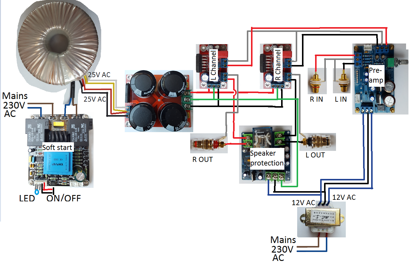
Am I right that the preamp is connected after the power amps?
I see that line inputs go straight into the power amps outputs, then the power amps inputs are connected to the speaker DC protection and then to the preamp inputs. The pre-amp output is driving the speaker terminals according to the diagram in post #1. I see a bunch of problems here.
Regards,
Oleg
I see that line inputs go straight into the power amps outputs, then the power amps inputs are connected to the speaker DC protection and then to the preamp inputs. The pre-amp output is driving the speaker terminals according to the diagram in post #1. I see a bunch of problems here.
Regards,
Oleg
Maby the AC 12V short is due to bad drawing? I don't see it
The problem is with the boards and not your layout.
The 12V AC ground (black wire) is connected though the Pre-amp to the output grounds, these are then connected to all the other grounds in the system.
The Speaker protection board was probably designed to be used with the 12V AC not grounded.
The problem is with the boards and not your layout.
The 12V AC ground (black wire) is connected though the Pre-amp to the output grounds, these are then connected to all the other grounds in the system.
The Speaker protection board was probably designed to be used with the 12V AC not grounded.
Thanks I will change it
Looks like you are missing one speaker output connector on each channel ? That is there should be 2 per channel. The associated wiring looks goofy also.
Of corse!
Can I just say that this is my first build, and I wan't to do it right the first time
And therefore there will be some brainfarts, and I didn't see it untill now! So thank you
I suggest you run the speaker protect PCB from the mains transformer in the Soft Start PCB. If it is the right voltage and if it has sufficient capacity to do both jobs.
That allows the transformer in the bottom right to only handle audio duties (the pre-amp).
The Soft Start has two relays.
One will be the delay to bring the main transformer on soon after switch ON.
The other is probably the main ON/OFF relay.
That main ON/OFF relay feeds power out via a terminal to the second relay.
You should be able to tap into that ON/OFF output and feed your other transformers from it.
That way one ON/OFF switch controls all your transformers (except the soft start transformer). This one will probably be ON all the time that you are plugged in.
Last edited:
I suggest you run the speaker protect PCB from the mains transformer in the Soft Start PCB. If it is the right voltage and if it has sufficient capacity to do both jobs.
That allows the transformer in the bottom right to only handle audio duties (the pre-amp).
Unfortunatly it's only rated to max 24V AC.
The Soft Start has two relays.
One will be the delay to bring the main transformer on soon after switch ON.
The other is probably the main ON/OFF relay.
That main ON/OFF relay feeds power out via a terminal to the second relay.
You should be able to tap into that ON/OFF output and feed your other transformers from it.
That way one ON/OFF switch controls all your transformers (except the soft start transformer). This one will probably be ON all the time that you are plugged in.
How is that different from connecting the other transformers to the OUT L/N terminal on the Soft Start?
- Status
- This old topic is closed. If you want to reopen this topic, contact a moderator using the "Report Post" button.
- Home
- Amplifiers
- Chip Amps
- Newbie's first post: A LM3886 project from a few years ago