I am thinking about replacing the power supply to my turntable motor - it's an experiment not a necessity, i.e. everything works as is, I just want to "play." I am looking for help to determine the specifications of the existing power supply.
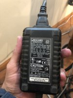
The AC goes through what looks like an SMPS that then connects to an AC power supply at the TT motor. The SMPS, which seems impossible to open, lists three possible voltage outputs, depending on the pins selected inside the case. If I could open the case . . . I could determine the output. The listed outputs on the case are
A) 5V with max amperage of 1.65
B) 12V with max amperage of 0.35
C) 21V with max amperage of 0.38
the motor driving the spindle lists 6A 125VAC.
I am contemplating replacing the PS in the unopenable casing, Unopenable because with lots of force it's not opening. NOT the motor spinning the spindle. I am assuming this is an algebra problem, if the the motor is 6A at 125VAC, that will tell me whether the PS is 5v, 12V or 21V. If I've assumed incorrectly here, I'd be happy to be educated, assuming there is a forum resident willing to do that.
In advance, thanks for looking.
Larry
Attachments
To give any meaningful tips, it would help to know what brand and model your turntable is, and why you want to change the power supply.
First question has to be 'what is the turntable' ?
A motor to spin a platter on a turntable needs only very minimal power, the 6A 125vac you mention would power a small vacuum cleaner.
Given the PSU is such an unusual one with multiple voltages suggests those might all be needed for circuit delivering 125 volt to the motor. For example it could power a crystal oscillator (maybe using 5v) and then a driver stage (12v) and finally an output stage (the 21 volts).
Its all an unknown without knowing more.
Unless you have a table with a 40 Lb lead platter, it does not need 6A!
Anyway, please no offence, but I think this is not the right first project for you. Do you have a multimeter? Have you found the schematics for the table?
What are you trying to do? As a remote supply is a nice 'quiet" way to do things.
Strange it would have an AC motor. Synchronous I suspect, but odd to me because there would be no easy to chane speeds unless pullies.
No...The pins are in the connector at the end of the cable, that's what the diagram is showing. Pins #1 and #2 are the 5 volt outputs, pin #6 is 12 volts, pin #8 is 21 volts, and the rest are the common return connections for all. There aren't any internal jumpers to switch output voltages.I am thinking about replacing the power supply to my turntable motor - it's an experiment not a necessity, i.e. everything works as is, I just want to "play." I am looking for help to determine the specifications of the existing power supply.
The AC goes through what looks like an SMPS that then connects to an AC power supply at the TT motor. The SMPS, which seems impossible to open, lists three possible voltage outputs, depending on the pins selected inside the case. If I could open the case . . . I could determine the output. The listed outputs on the case are
A) 5V with max amperage of 1.65
B) 12V with max amperage of 0.35
C) 21V with max amperage of 0.38
the motor driving the spindle lists 6A 125VAC.
I am contemplating replacing the PS in the unopenable casing, Unopenable because with lots of force it's not opening. NOT the motor spinning the spindle. I am assuming this is an algebra problem, if the the motor is 6A at 125VAC, that will tell me whether the PS is 5v, 12V or 21V. If I've assumed incorrectly here, I'd be happy to be educated, assuming there is a forum resident willing to do that.
In advance, thanks for looking.
Larry
Mike.
That's just a generic computer DC power supply, the specifications are on the label. The turntable probably
only uses one of those three DC voltages, all of which are present on the output connector, and has a DC motor.
The other connector pins in the turntable may not even be connected. But it's best to leave this alone,
as it is not intended to be opened, and damage could easily be done. You should play with something else instead.
Last edited:
I appreciate you all providing your knowledge and experience. The table has performed without interruption for nearly 20 years. It continues to perform well. I guess, best efforts to the contrary, I've stated my question poorly. I am looking to try a different, aftermarket power supply to see if it elevates the table's performance. I am unable to identify an LPS that will fit my bill because I don't know what specifications it needs to meet, and thus my question (did I state my issue better now?) The platter weighs between 5-8 lbs.
I wasn't sure I'd get responses, so I avoided attaching too many pictures. I've attached a cropped image of the motor spinning the platter. FWIW
Johnmath: Why change it? Play. Fiddling. "Because," to be responsive and yet unhelpful. "Need" is not an issue here. I wanted to fiddle with the power supply to see what performance might open up.
Mooly: TT is Amazon Model 2. Company is out of business. Excuse me, I emailed the manufacturer last just after my father passed, and thought the website was down. I am mistaken. I'm not sure if the designer is still responding to questions, but I emailed him just now. Mooly, thanks for your question. I provided as much measurable information as I could. The details are of the stock table, i.e. no mods by me or anyone else. I cannot answer the questions you raise in your third paragraph - that's why I'm asking for help.
Tvrgeek: "Need" seems to miss the point. The information I relayed reflects how the table was designed and delivered. I have a multimeter; set to measure V, I read the output at 5.28VDC. There are no known schematics, but I may get more information from the designer, if he's not sailing the seven seas now - he retired three years ago. FWIW, I'm not intending to design a power supply, but to try an off the shelf LPS, if such is available at a price I decide is reasonable. The table has a toggle for 45 and 33 rpm. If a proper power supply can be identified, I have skill and money to pay for one - I'm not designing or building one. I'm looking for plug and play.
Mike: I'm not sure what to deduce from your reply. It appears you're saying all the pins, with differing settings are in the connecting cable. So . . . are you saying I need three power supplies? Or another similarly configurable power supply?
Rayma: I thought the PS was from a computer. (ebay was the best, easy source of info on the Hughes PS) I was hoping for a bit more instruction from people with more knowledge than me. I do appreciate your assessment, however.
So the answer is not "because", the answer is "to see what performance might open up".Johnmath: Why change it? Play. Fiddling. "Because," to be responsive and yet unhelpful. "Need" is not an issue here. I wanted to fiddle with the power supply to see what performance might open up.
The first reference I found for Amazon 2 turntables says that they use a DC motor. To a some extent that configuration will seperate the quality of the supply from the quality of the torque output of the motor, assuming the designer of the motor controller has done a good job of both the functional circuit design and the actual physical layout. Unfortunately that is not a safe assumption. A high quality low noise supply could be beneficial, and I have often built the same for high end turntables.
I would hazard a guess that only the 21V 0.38A section of the supplied computer SMPS is used. You can check this by seeing which pins are actually connected inside the turntable plinth. To make a high linearity low noise linear power supply is relatively simple, but more often than not in the real world the physical implementation often fails miserably and performance falls drastically below what is achievable.
I would hazard a guess that only the 21V 0.38A section of the supplied computer SMPS is used. You can check this by seeing which pins are actually connected inside the turntable plinth. To make a high linearity low noise linear power supply is relatively simple, but more often than not in the real world the physical implementation often fails miserably and performance falls drastically below what is achievable.
Belts may perish, lubrication may dry out but an SMPS supply either works or doesn't.
Give it a clean, lubricate if you have the correct grade of oil and enjoy for another 20 years.
Give it a clean, lubricate if you have the correct grade of oil and enjoy for another 20 years.
johnmath:
Here is information on my tt
Bearing: Inverted steel/ceramic with oil reservoir
Drive: DC-Motor with LSC
Speed: 33/45 rpm electronic adjustable with fine tuning
Power supply: external switching power supply
"LSC" means "linear speed controller."
This is the link, if you want to look further: http://amazon-audio.de/Engl_Ama_A2.html
Is there a connector at the end of the power supply cable? Does that connector have pins sticking out of it? And does that connector mate with a socket on the turntable?Mike: I'm not sure what to deduce from your reply. It appears you're saying all the pins, with differing settings are in the connecting cable. So . . . are you saying I need three power supplies? Or another similarly configurable power supply?
Those three voltages are all contained in that cable and can be read with a DMM at the pins. You should be able to read the voltages between the various voltage out pins and the common pins. There is nothing to adjust...as you said it's a sealed unit, just like they all are.
Mike
Mike:
There is a heat shrunk cable (#) wire exiting the SMPS. It terminates at a barrel connector. There are no pins inside or out at that end.
I've partially pried open the SMPS case. The # cable is soldered to a circuit board inside the SMPS case.
If there are jumpers or pins (same thing?) inside the case they're not visible to me.
The amount of attention to detail expressed on the Amazon Audio website implies that their drive electronics were likely exemplary. However don't let that stop you from building a linear regulated supply should you wish to. The first step is to understand which voltages are actually used, because I think the supplied unit was chosen for availability and cost, not necessarily to take advantage of all three output sections.
This is roughly what I typically do. Build replacement supply in shielded and grounded case, using oversize toroidal transformer (low external field), properly implemented low noise regulated supply with floating (but RF bypassed) outputs, low loss low inductance (heavy conductor) cable with shield connected to electrical chassis ground, plug to fit turntable mechanically and aesthetically. Then for the turntable I rewire internals as necessary to match quality of new power supply minimising stray fields, repair or restore / recap control electronics, check control circuit servo for stability, service motor, belt and main bearing (replace bearing ball with ceramic if steel).
Below is a photo of a power supply I built for a Goldmund Studietto (small enclosure behind the wineglass). I made another matching one for the client's Michell Iso phono stage as well.
For what it's worth I found a fault (and its fix) in the Linn Valhalla electronic supply that causes instability at start-up and consequently poor starting torque. It takes about 5 seconds for the circuit to stabilise, no wonder Linn owners often give their platters a gentle push start! Ironically the fault has been copied by other manufacturers of electronic drives for LP12s around the world, like Hercules for example. The Linn service agent in Australia was astounded when I showed him the fault and repair; everyone just assumed Linn knew what they were doing. Best not to make assumptions!
Last edited:
That is the rating of the switch, not the motor. Essentially the switch is suitable for any voltage up to a maximum of 125V and can switch a current up to a maximum of 6A at that voltage. It may have another rating on the other side, e.g. 250V 3A. In this case it will be switching low voltage from the supply.... if the the motor is 6A at 125VAC...
In the photo the switch appears to be connecting one of two different wires from the controller, with a centre off and with a third (common) wire going direct to the motor. I guess that is 33 1/3 - Off - 45
Yup -- the secret to assessing the power supply requirements is right at the jack where the Hughes PS plugs in. Likely only some of the pins are terminated: That's where you'll find useful measurements.
Even in the very unlikely event that all 3 voltages need to be provided, it's still only 20,43 watts -- shouldn't be too tall of a challenge.
There is still the possibility that this project is a little tall for you presently -- but some say that's where the fun is! You haven't mentioned what aspect of the turntable's performance you hope to improve.
Post those pin connections / voltages and we'll go from there.
Regards

Is that a picture of the plug that connects the power supply to the turntable? If so, there are only two connections, the pin and the outer shell. That means only one of the three voltages from the Hughes SMPS is being used. Connect a meter to the inner and outer connections of the plug and you can read the voltage. According to Amazon Audio's website, the SMPS supplied is capable of ten times the current that the turntable actually needs. Those two pieces of information are all that's needed to specify a new supply design.
Ah, now I see why all the confusion, they modified the power supply by changing the output connector...how dare they! 😉
Mike
Mike
- Home
- Amplifiers
- Power Supplies
- Newbie with a dumb question