I am going to try this! My heater runs to earth. Its going to be a while before I do it so I cant answer by trial my next question. Is this why I hear music play when I run the valve with just the heaters running and NO anode voltage?
No, this is only to protect valves to not exceed Vkf.
Just double checking: you have the negative pin of the 100uf cap on heater ground?
No, negative pin of cap to ground, positive pin to heater ground.
Heater ground is at +B/4 VDC, but 0 VAC via the cap.
Here are the schematics of the DAC. Signal stealing from Vouts is Ok.
It's the Pcb ground when im not 100% sure i've done it properly.
Lukazs insist on "PCB ground from the point closest to the DAC ".
Have i done it right using Pin 15?
An externally hosted image should be here but it was not working when we last tested it.
An externally hosted image should be here but it was not working when we last tested it.
It seems to me that you must use analog ground, pin 22.
Humble advice
Your DAC outputs seems ready to use 2V standard, an amp here only would increase distortion and signal level.
When DAC outputs are amplified by OPAMPs, you can replace them with your preamp, but this is not the case.
I would do the preamp in a separate case as a line preamp.
Your DAC outputs seems ready to use 2V standard, an amp here only would increase distortion and signal level.
When DAC outputs are amplified by OPAMPs, you can replace them with your preamp, but this is not the case.
I would do the preamp in a separate case as a line preamp.
Ok , is there any harm on keeping also Pin 15 grounded ?
Probably you would short circuit the IC.
UPDATES:
I changed R2 to the specified value 270k Ohm , and added a 270Ohm grid resistor and i grounded everything exept the Dac board.
Well yes , now the bass is there....but its not sounding good yet. Now i can really notice the big amplification difference between stock Rca and Tube Rca.
I think the signal is overloading my Yamaha rxv 667 inputs !!
Remember when using only 270Ohms in R2 , the sound was harsh at highs and lacked bass?
Well now the highs are not harsh , but they are still distorted , sounds like "clipping distortion" , like overloading.
I see 2 possible escenarios: 1- Remove grid stopper / lower the value of R2 ?
2-Change to a Cathode Follower to get only 1:1 amplification of the 2v out from DAC
Could somebody provide me a nice shematic for Cathode Follower , for 6N6P and V out Dac? I know Lukasz must have uploaded one on his website but i always have a hard time to figure out his handmade drawings 🙁
Here is a Cathode Follower shematic from Lukasz , i think he is using 6N6P too !
Should i follow the same values for RG -R1 -RK ?
Sadly there is no info about Caps values , i guess they must be the same as SRPP....
Should i follow the same values for RG -R1 -RK ?
Sadly there is no info about Caps values , i guess they must be the same as SRPP....
An externally hosted image should be here but it was not working when we last tested it.
I went to test it again with some music . When playing trough "Pure Direct" with the Yamaha , all the distortion dissapears... I dont know what is wrong then. If you switch to "straigt/normal" mode the sound is COMPLETELY different , super distorted and cliped.
Could it be AC interference? Because of the "bad design at the PSU "?
I must find a solution for it to work properly at any circumstance
Could it be AC interference? Because of the "bad design at the PSU "?
I must find a solution for it to work properly at any circumstance
Last edited:
That's what happens; your CD player has an output of 2 VRMS, but a standard mastered CD recording is 16 dB (average) below the maximum level possible, so you have about 320 mVRMS at the output, a 6N6P in SRPP has a gain of about 10 in unbypassed version, then your 320 mVRMS are now 3.2 VRMS, that is a lot and you are saturating the power amp.
Standard output of your CD player also has low impedance, so adding a cathode follower would only add distortion and noise.
Humble advice part2
Make a line preamp with a volume control in a separate enclosure and enjoy your Lampizator, you would use your CD player normally, connected to the preamp from the RCA output sockets.
Unfortunately, with your particular CD player, the mod is totally "al pedo" (for nothing)
Attachments
Last edited:
I think its an earth/ground problem. I've listening to it in "Pure Direct" for 1 and 1/2 hours , and it sounds BEAUTIFUL . Once i solve the ground problem and mod the PSU there won't be any hiss/amplification of noise in straight mode.
Pink Floyd The Wall and Charly Garcia both benefits night and day of this high gain amplification , is pure bliss and glory ! But like you said .....3.2 VRMS is maybe too much for pretty much everyother recordings , sometimes i could hear clipping because of overloading.
So i will probably switch to Cathode Follower for 1:1 gain.
I can still use my CD Player normally , the stock RCA are still working fine. Thats how i benchmark between the two outputs.
I'll post the progress as soon as possible !
Unfortunately, with your particular CD player, the mod is totally "al pedo" (for nothing)
Hey ! please don't "bardees" my little player jajaj ! Its not that bad after all....sure the transport is plastic type and cheappy one....but the DAC is MASH , very strong and clean output .
When i bought it i thoug it was the SLPG440A...only after opening it i discovered mine is 440 and they are not the same 😱 !!! I didn't knew there were 2 versions of the player ,the first a princess player , and the latter lazy player.......i was looking for the one with the nice CDM 4/19 and MN6474 (440A) 🙄 Better luck next time...
Your CD player is OK, the problem is your mod, all the ways conduct to more distortion and noise, but please, don't use a cathode follower, make an attenuator before the Lampizator, if you don't desist of the mod.
A good cathode follower is very tricky to design properly, and all of them sounds ugly for my taste.
Edit: Seems to me that your amp has a line input, 200 mV sensitivity, then you must use the direct input in order to not overload it.
Last edited:
What about SY's approach to a cathode tube buffer in this thread
http://www.diyaudio.com/forums/tubes-valves/169150-cathode-follower-tube-buffer-using-6n6p.html
I just been sat here with Morgan Jones trying to work one out for you. Too complicated for me.
http://www.diyaudio.com/forums/tubes-valves/169150-cathode-follower-tube-buffer-using-6n6p.html
I just been sat here with Morgan Jones trying to work one out for you. Too complicated for me.
Now is currently working without distortion in "Pure Direct" mode.
What do you think about Anode Follower Triode ? In that setup only one half of tube per
channel is used. So i could build it with just 1 6N6P tube. Is it still high gain like SRPP?
About Cathode...both Lampizated Technics SLPS700 and Yamaha CDX 480 by Lukasz are done this way , since they have MASH Dac with a good 2V Output. Thats why i want to try it. He's got good results
Last edited:
I just been sat here with Morgan Jones trying to work one out for you. Too complicated for me.
Nice !! Nice !!
What about SY's approach to a cathode tube buffer in this thread
http://www.diyaudio.com/forums/tubes-valves/169150-cathode-follower-tube-buffer-using-6n6p.html
I just been sat here with Morgan Jones trying to work one out for you. Too complicated for me.
While I admire and respect SY designs, I hate cathode followers. 😀
Now is currently working without distortion in "Pure Direct" mode.
What do you think about Anode Follower Triode ? In that setup only one half of tube per
channel is used. So i could build it with just 1 6N6P tube. Is it still high gain like SRPP?
About Cathode...both Lampizated Technics SLPS700 and Yamaha CDX 480 by Lukasz are done this way , since they have MASH Dac with a good 2V Output. Thats why i want to try it. He's got good results
If you insist with the mod, SRPP is THE way to go.
setting aside all opinions of which valve stage is right. Would these values for a sinple cathode follower work to give Stef a buffer
I have no computer skills to do it as a diagram, given up with the load line and Morgan Jones!!!
Stef you have 180volts power supply
I think you are to cut that in half ie 90volts
I look on the 6n6p datasheet and on the first graph of Ia=f(Ua) I take 15ma because of the 90volts and the -2volts of the DAC
SO
the Anode resistor is 90v/0.015A=6000 ohms=6Kohms
its power should be 6000*0.015*0.015=1.35 so at least 2w
Cathode bias resistor is grid voltage/current ie 2/.015=133 ohms so 130 ohms for easiness
its power should be 133*.015*0.015=0.03 so 0.25 (1/4) watt
the grid resistor to ground , I am guessing is 270K
the output cap resistor is 100k to 1M
input cap is about 1uf
output cap is about 2.2uf (I have no idea how they work it out)
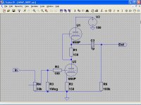
 here is a photo of the schematic. If some one who actually knows what they are doing could tell me if the figures are right?
Dear Alan , the power suply values are wrong, mine is actually 140v .
And i think 15mA would be too much , what about something like this to prolonge Tubes life:
Power suply voltage to Anode 140v , so there is a 70v drop out. 6N6P I=10mA Ug -4v
Ra 70v/10mA. =7K Ohm for Anode
Rk. 4v/10mA.= 400 Ohm for cathode
Grid resistor....i dont know how to calculate
Output cap resistor why did you choose 100k to 1m values ?
I hope this numbers workout 🙂
Last edited:
I chose 15ma because they say its the valve's sweet spot. Plus when I looked at the curves on the datasheet it worked well with the graph.
Your dac gives 2v not 4v
the grid resistor and output resistor are values I see often used. I have no idea how to calculate them. Morgan Jones may as well of written his book in Mandarin as far as I am concerned. I have no time to do an electronics degree. So I only can experiment. I was hoping someone with proper knowledge would say yeah or nay.. Also I am not sure if the load of the amplifier it is connected to plays some role in the figures...Blind leading the blind here I think.
- Status
- Not open for further replies.
- Home
- Amplifiers
- Tubes / Valves
- Newbie to SRPP and Tubes , 1 question.