Blind leading the blind here I think.
Haha the situation is hillarious
If nobody more skilled replies i'll then just start a new post asking for verification of this Cathode follower , since the distortion/hum problems are already solved , what im looking for is to avoid amplifier input overload (hence a 1:1 gain design)
Leaving the design of correct values for Cathode Follower there's another thing......my transformer has a 12v secondarie for heaters (thats ok for SRPP with two TUBES).
I think im going to have a hard time to get 6.3v from that 12v secondarie. Some people advices not to use a regulator to step down to 6.3v because its going to burn , Is it true? There must be a good regulator out there for this task....
I think im going to have a hard time to get 6.3v from that 12v secondarie. Some people advices not to use a regulator to step down to 6.3v because its going to burn , Is it true? There must be a good regulator out there for this task....
Hi,

1. SRPP: amplification factor (mu) /2. So, if a triode has a mu of say 30 that will be halved when used as an SRPP circuit.
Zout, output impedance is lowish. Much lower than a plate follower.
This circuit is a stacked topology so it requires two triodes, one on top of the other. Mind heater to cathode insulation on the top tube, incect B+/4 into the heater supply.
2. CF or cathode followers 😉 : gain is close to unity but not quite so you have a small insertion loss. It's a buffer, has low Zout so it is suited to drive longish, capacitive interconnects and low input impedances such as found in sand amps.
100% internal feedback means it will be pretty much distortionless as is.
3. Plate follower or anode follower: high gain possible , close to mu. High Zout so not well suited to drive low Zin. Bypassing the cathode resistor with a highish value cap reduces Zout somewhat and optimizes gain at the expense of extra distortion.
Re the 12V heater xformer, using a FW bridge rectifier type you'll end up with roughly 12*1.44 = 17 VDC, after RC filtering and regulation you can obtain 6.3VDC for the heaters. Just make sure the xformer has ample current rating. I usually go for twice the nominal heater current demand.
IMHO, if this DAC has built in amplification into the chip, the only option is the CF, or the SRPP if your system is inefficient (speakers for instance). The SRPP may still overload the amp occasionally though.
So, in a nutshell, the whole exercise is pretty much "al pedo" in this case.
Ciao, 😉
I donth think its "al pedo" at all. The SRPP design im using right now improved the sound of the player. Its much more analog sound and less digital.
My speakers are very efficient , 93db , so the SRPP has a lot of gain and yes , with most albums it clips sometimes (not quite often).
So i want to try Cathode Follower to solve the overload to the amp. And i want to finish the exercise. Am i then clear with everything?
What i need right now? A good schematic to follow and build the Cathode Follower with the right values considering im using 6N6P.
Thanks for your reply Frank !
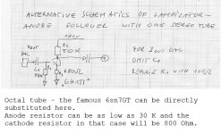
That is not an anode follower. It is a degenerated grounded cathode.
So what exactly does the circuit do?? It sounds good
It's a voltage amplifier, used where none is needed. It adds noise, distortion, and excess gain. It also has high source impedance to help make the frequency response non-flat. It will certainly be an effects box; if you like the effect, go for it.
Have you tried this circuit?
I must have bench tested about 6 circuits before I tried this one. For MY Cd player, which is a Denon DCM-390, V-Out DAC, 2V. This one was the Sweet spot.
Hi ! Im happy you found something that works for you and like the sound !
If you read my other post , i've managed to make it work in Cathode Follower. I've uploaded my shem.
I also made the lampizator for some cd players. My advice to improve the lack of bass is to check the pdf Dietmar´s document in fetishizator section of lampizator site. He says for " Input resistor R2 should be about 10times the value of the specified inner resistance, mentioned in the datasheet as “output resistance” f.e." " The inner resistance refers to dac chip. In my case changing 250K ohm to 120K made a whole difference.
- Status
- Not open for further replies.
- Home
- Amplifiers
- Tubes / Valves
- Newbie to SRPP and Tubes , 1 question.