Hello , im a newbie trying to bypass my Cd player PCB output stage with some 6N6P Tubes in SRPP fashion , following Lukaz Fikus schematics , aka LAMPIZATOR.
But there is something i don't really understand about this schematics (clic to full size) , the Rca outs....
Circled in Green is where i have a trouble. There is only 1 out to the Rca , and the player has 2 since is stereo. Is there something missing in the schematics?
How should i proceed to take the Left and Right signals ?
I tried to guess how it should be and i came with this 2 modifications of the schematics , but i don't know if any of them are correct
And here is the only good picture i could find of the Lampizator in SRPP using 6N6P Tubes , as you can see , he takes the Right signal from 1 tube and the Left signal from the other one. But thats not how he shows it in the first shematics at the top of the post.
But there is something i don't really understand about this schematics (clic to full size) , the Rca outs....
An externally hosted image should be here but it was not working when we last tested it.
Circled in Green is where i have a trouble. There is only 1 out to the Rca , and the player has 2 since is stereo. Is there something missing in the schematics?
How should i proceed to take the Left and Right signals ?
I tried to guess how it should be and i came with this 2 modifications of the schematics , but i don't know if any of them are correct
An externally hosted image should be here but it was not working when we last tested it.
An externally hosted image should be here but it was not working when we last tested it.
And here is the only good picture i could find of the Lampizator in SRPP using 6N6P Tubes , as you can see , he takes the Right signal from 1 tube and the Left signal from the other one. But thats not how he shows it in the first shematics at the top of the post.
An externally hosted image should be here but it was not working when we last tested it.
6N6P is a double triode.
Always have a look at the datasheet first: http://www.lampizator.eu/UPGRADE/RU-6N6P.pdf
You just need two identical circuits for left and right.
Always have a look at the datasheet first: http://www.lampizator.eu/UPGRADE/RU-6N6P.pdf
You just need two identical circuits for left and right.
Neither of the "modifications" are correct. You need to repeat the entire circuit for each channel.
Some notes:
1. You'll have to consider how the heaters are powered so as not to exceed heater-to-cathode voltage ratings.
2. You'll need to connect a resistor from the "hanging" end of each output cap to ground to prevent major bangs as the cap discharges. It should be large enough not to roll off the bass.
3. This will not be a low distortion circuit! Strictly speaking, it's also unlikely to be an SRPP, since the load will not have been chosen to get a distortion null. This stacked topology is very problematic (except when used as intended, for swinging large voltages into low and reactive loads, none of which is applicable here) and very fashionable.
6N6P is a double triode.
Always have a look at the datasheet first: http://www.lampizator.eu/UPGRADE/RU-6N6P.pdf
You just need two identical circuits for left and right.
Thanks Manta ! I knew it was a double triode , but i just made a mistake reading the shematics (my bad).
So it means that the V1 circles are just the 2 triodes from one 6N6P tube ? I though they were two diferent 6N6P. Thats why i call my self a Newbie 😛
2. You'll need to connect a resistor from the "hanging" end of each output cap to ground to prevent major bangs as the cap discharges. It should be large enough not to roll off the bass.
Chokesrules member made a post about this sometime ago
http://www.diyaudio.com/forums/tubes-valves/220803-newbies-beware-lampizator-srpp-pdf.html
he basically says this:
"you need to wire in a 50K to 1M resistor so the capacitor polarises instantly"
I don't know a topology that meets many qualities together, and be as merciful with the designer as the despised SRPP.
Most common argument against SRPP is its load dependent distortion, but this is almost meaningless because the minimum distortion is achieved with ridiculously low loads.
I use it as input stage, even in phono preamps, as line stage, as driver stage, always with great success.
However there is a possibility that I have not ear nor to ring the bell. 😀
email
Hi yes, in answer to your email. That thread was because I had no "hanging resistor" after the cap. I found high voltage on the positive of the interconnect cable at switch on. People posted back saying this is not the case. That it has something to do with way the multimeter works.
I am not qualified or any way intelligent. I just do things by trial and error. BUT!!! When my multimeter says high voltage on that pin I sure as hell am not going to touch it!!!! Let the people who say its safe, when the meter reads 240volts dc, touch it and post a you tube video of them doing it.
I cured the problem by putting a "hanging resistor" in...The values I posted 50K to 1Meg was because I see this range of values often used in this manner. You will have to experiment ..Follow the signal through the output capacitor then solder a resistor from the capacitor's output pin to ground. I use a 2 watt to be absolutely certain the resistor has enough power rating.
The way I see it is . A little knowledge is a dangerous thing. Therefore you should go about this hobby as safely as you know how to
Don't forget as well to use a bleeder resistor in your power supply so the caps drain quickly to 0volts when you switch off
Don't forget to check your chassis is earthed
Remember to always check your capacitors with a multimeter before you do "any work". Even bleeder resistors take time to drain capacitors.
To make things clearer for you. You need two 6h6p valves, and each channel uses the two triodes that are housed in one valve (envelope)
So you need 2 copies of the lampizator posted circuit. One for left one for right.
If you get it going and your DAC has left and right +/- outputs try his balanced circuit its much better
Everyone seems to hate this Lampizator circuit but for me it gave a great upgrade in sound and the start of a great hobby...
However there is a possibility that I have not ear nor to ring the bell. 😀
JAJA !! Don't worry , your ears are not the problem 😀 . I would trust Lukasz Fikus, chief designer -my ears easily ! He is not electronic educated but elecrical engineer , he would break tens of rules that an electronic engineer would never break to get his products to the audio Nirvana. He stands for the SRPP !!
Estamos en contacto amigo !
Don't forget to check your chassis is earthed
Thanks ! Yes , everything will be to be star grounded 😀 And don't worry about the 6N6P ,i made a stupid mistake when interpreting the schematics , now i got it !
Hopefully i'm finishing it tomorrow or Thursday
UPDATES :
The SRPP 6N6P circuit is up and runing.......but not without some problems 🙁
Everything was measuring Ok.......BUT !! When i quickly connected the tubes to the player Dac and the RCA to the amp , i got HUM (this does not matter since i did not connect ground , i just wanted to test the sound and its verly low hum anyway) , NOISE (HF noise i think) and DISTORTION , compared to the stock Rca from the player.
The sound from the Tube was bigger , with better separation and life , but at the same time very Harsh and thin on Bass , it lacked Bass. Another thing that caught my attention was that this SRPP with 6N6P was "supposed to amplify the signal a lot " but when swapping between the diferent rca outputs , both the stock player and Lampizator outputs had the same volume/level. I think it should not be this way.....
From the very Fikus Lampizator tutorial there is a "Possible Problems" section i will quote
"
Noise
Noise is usually a result of digital artifacts (oversampled) to frequencies mostly above hearing) not filtered well after DAC chip. To filter them out, add a RCR filter after a DAC (of voltage DAC type). From DAC Vout put a series resistor – maybe 2K, then cap to ground and then another series resistor of 2K or similar. Size of capmust be around 110nF. A nanofarad is 1/1000 of a microfarad.
Ceramics are the best.
High distortions of sound
This can be aresult of: current type of lampizator seeing too large resistor. TDA1541 tolerates maximum of 100 Ohms, BB56 tolerates 1 K, PCM1702 tolerates 50 Ohm, and so on. try for yourself the right one. Too small
resistor and the sound will be aenemic.
To put things on perspective.
Player: Technics SLPG440 with
MASH [FONT=Courier New, Courier, monospace]MN66271RA[FONT=Courier New, Courier, monospace] Voltage out [/FONT][/FONT][FONT=Courier New, Courier, monospace][FONT=Courier New, Courier, monospace][FONT=Courier New, Courier, monospace]Dac[FONT=Courier New, Courier, monospace] ,[FONT=Courier New, Courier, monospace]which is located under the cd transport.[/FONT][/FONT][/FONT][/FONT][/FONT]Choke : 80w 220v with 2 secondaries (110v and 12v)
Tube : 6N6P noval ( nominal current is 750 mA @ 6,3 V)
Circuit followed : SRPP as Lampizator tutorial.
Amplifier : Yamaha Rxv-667
Here is the circuit , with the current values im using right now.
So this way i got 6.3v on each tube heaters 🙂 -- Dc on the Anode suply is about 140-150v , and the anode of second tube half is exaclty 1/2 of Anode supply votage , so everything is measuring Ok this far...
And here is a little different shematic (with other values , not the ones im using in my player-circuit) if some of you can't read the handmade drawins below.
This is a CAD circuit , so its much easier to read. Note on the resistor in between the output Capacitor and the Rca....some discution has been made about this , about including that resistor to prevent major bangs as the cap discharges..
Could that be the reason of the high Noise and Distortion? Or is it just a safety measure? How much is large enough and how much is "too much" in values ?
Going back to the main issue here is where i "may think" the problem arises:
1- High distortion due to an improper value of a resistor , for example R2 270Ohm too large? But i think this only aplies to I type DAC , am i wrong?
2-The fact of not using "metal film" resistor for R1 and R2 ?
3- HF Noise due to lack of filtering after DAC ? Then try to add a RCR filter
4- SRPP signal is very strong and is overloading the Amplifier inputs ? I don't think this is a problem because both signals (stock and tube) have an identical level (to my ears). But if this is the problem , may change to a Cathode Follower topolgy with 1:1 amplification?
4- Something going wrong when i soldered the Dac Vout legs to the input capacitor of the tubes? (Of course i didnt solder directly to the legs , i soldered to the next resistors on the pcb leads after the Dac legs.)
I may also discard this because the amp is playing music so the signal stealing might be Ok .
Here are some pics of the assembly. I know it does not look very Pro or Clean ...thats because i had lots of trouble doing it.....my brother was supposed to know some electronics but was not a big help at all...
Signal stealing from dac unbeneath the transport
I don't hear any hiss which is usually due to oscillation . When you hit pause its very quiet , even though you hear Hum because its not grounded yet.
What i hear is very Harshy and Bright music with lack of Bass. Even you con feel more "air" and space , its not pleasant to listen , i would not listen even to 1 song with it.
Lukazs lampizated a Yamaha CDX-480 player , which has the same Dac as mine
( [FONT=Courier New, Courier, monospace]MN66271RA) and he higly recomends it ! So i don't think is a player issue , i must be doing something wrong or missing something.
Thanks you in advance if you had the patience to read this hole book of mistakes 😀
[/FONT]
Ceramics are the best.
High distortions of sound
This can be aresult of: current type of lampizator seeing too large resistor. TDA1541 tolerates maximum of 100 Ohms, BB56 tolerates 1 K, PCM1702 tolerates 50 Ohm, and so on. try for yourself the right one. Too small
resistor and the sound will be aenemic.
To put things on perspective.
Player: Technics SLPG440 with
MASH [FONT=Courier New, Courier, monospace]MN66271RA[FONT=Courier New, Courier, monospace] Voltage out [/FONT][/FONT][FONT=Courier New, Courier, monospace][FONT=Courier New, Courier, monospace][FONT=Courier New, Courier, monospace]Dac[FONT=Courier New, Courier, monospace] ,[FONT=Courier New, Courier, monospace]which is located under the cd transport.[/FONT][/FONT][/FONT][/FONT][/FONT]Choke : 80w 220v with 2 secondaries (110v and 12v)
Tube : 6N6P noval ( nominal current is 750 mA @ 6,3 V)
Circuit followed : SRPP as Lampizator tutorial.
Amplifier : Yamaha Rxv-667
Here is the circuit , with the current values im using right now.
An externally hosted image should be here but it was not working when we last tested it.
Left and Right tube are connected to the heaters in series of 12.6volts dc! just like Lukazs said , these voltages get adjusted by a 5W 1Ohm resistor from heater rectifier Plus to the second Capacitor Plus (heater output)So this way i got 6.3v on each tube heaters 🙂 -- Dc on the Anode suply is about 140-150v , and the anode of second tube half is exaclty 1/2 of Anode supply votage , so everything is measuring Ok this far...
An externally hosted image should be here but it was not working when we last tested it.
And here is a little different shematic (with other values , not the ones im using in my player-circuit) if some of you can't read the handmade drawins below.
This is a CAD circuit , so its much easier to read. Note on the resistor in between the output Capacitor and the Rca....some discution has been made about this , about including that resistor to prevent major bangs as the cap discharges..
Could that be the reason of the high Noise and Distortion? Or is it just a safety measure? How much is large enough and how much is "too much" in values ?
An externally hosted image should be here but it was not working when we last tested it.
Going back to the main issue here is where i "may think" the problem arises:
1- High distortion due to an improper value of a resistor , for example R2 270Ohm too large? But i think this only aplies to I type DAC , am i wrong?
2-The fact of not using "metal film" resistor for R1 and R2 ?
3- HF Noise due to lack of filtering after DAC ? Then try to add a RCR filter
4- SRPP signal is very strong and is overloading the Amplifier inputs ? I don't think this is a problem because both signals (stock and tube) have an identical level (to my ears). But if this is the problem , may change to a Cathode Follower topolgy with 1:1 amplification?
4- Something going wrong when i soldered the Dac Vout legs to the input capacitor of the tubes? (Of course i didnt solder directly to the legs , i soldered to the next resistors on the pcb leads after the Dac legs.)
I may also discard this because the amp is playing music so the signal stealing might be Ok .
Here are some pics of the assembly. I know it does not look very Pro or Clean ...thats because i had lots of trouble doing it.....my brother was supposed to know some electronics but was not a big help at all...
Signal stealing from dac unbeneath the transport
An externally hosted image should be here but it was not working when we last tested it.
An externally hosted image should be here but it was not working when we last tested it.
An externally hosted image should be here but it was not working when we last tested it.
I don't hear any hiss which is usually due to oscillation . When you hit pause its very quiet , even though you hear Hum because its not grounded yet.
What i hear is very Harshy and Bright music with lack of Bass. Even you con feel more "air" and space , its not pleasant to listen , i would not listen even to 1 song with it.
Lukazs lampizated a Yamaha CDX-480 player , which has the same Dac as mine
( [FONT=Courier New, Courier, monospace]MN66271RA) and he higly recomends it ! So i don't think is a player issue , i must be doing something wrong or missing something.
An externally hosted image should be here but it was not working when we last tested it.
Thanks you in advance if you had the patience to read this hole book of mistakes 😀
[/FONT]
I never had any success with the heaters in series. They showed different operating voltages and the voltages drifted all over the place. Too close to 7volts for my liking. I used a lm317 . I use one per heater.
Resistor type made only minor differences in sound don't worry
I used 2,2uf to 10uf on output capacitor
I ran a lampizator for ages without that output cap resistor (turn your amp on last, unplug it first)
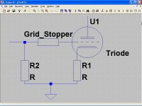
Its hard to tell on your diagram,, but are you using 270 "R ohms" as a grid stopper resistor??If you are it should be 270"Kohms"
R1 should be 200 to 300R ohms according to Lukasz
Resistor type made only minor differences in sound don't worry
I used 2,2uf to 10uf on output capacitor
I ran a lampizator for ages without that output cap resistor (turn your amp on last, unplug it first)
Its hard to tell on your diagram,, but are you using 270 "R ohms" as a grid stopper resistor??If you are it should be 270"Kohms"
R1 should be 200 to 300R ohms according to Lukasz
Last edited:
Yes , i made a mistake with R2 , it should be 270"Kohms"
I was distracted when buying the components , my bad.
I was distracted when buying the components , my bad.
Yes , i made a mistake with R2 , it should be 270"Kohms"
I was distracted when buying the components , my bad.
That's the reason of thin on bass, try at least a 100K or higher resistor in the output for "discharge resistor".
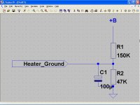
Hum surely comes from your long cables that connect the valves, they pick hum from AC fields, your PSU is a poor design, you can reduce ripple with more filtering, and heater supply ground must be elevated to +B/4, try a voltage divider, say 150K in series with 47K paralleled with 100 µF.
6N6P is a high transconductance valve, maybe you must use a grid stopper (100 Ω to 300 Ω) on the bottom triode in order to avoid HF oscillations.
popilin could you explain " and heater supply ground must be elevated to +B/4, " so I can understand
popilin could you explain " and heater supply ground must be elevated to +B/4, " so I can understand
In SRPP topology, top triode cathode is at about +B/2, bottom triode cathode is at about 0V, so in order to not exceed Vkf, heater supply ground (or its positive) must be elevated to +B/4
Attachments
I am going to try this! My heater runs to earth. Its going to be a while before I do it so I cant answer by trial my next question. Is this why I hear music play when I run the valve with just the heaters running and NO anode voltage?
Just double checking: you have the negative pin of the 100uf cap on heater ground?
Just double checking: you have the negative pin of the 100uf cap on heater ground?
6N6P is a high transconductance valve, maybe you must use a grid stopper (100 Ω to 300 Ω) on the bottom triode in order to avoid HF oscillations.
By "grid stopper" do you mean R1 on the bottom triode ? If thats the case , im using 150Ω
By "grid stopper" do you mean R1 on the bottom triode ? If thats the case , im using 150Ω
No, between 270K input resistor and the grid of the bottom triode.
Attachments
Here are the schematics of the DAC. Signal stealing from Vouts is Ok.
It's the Pcb ground when im not 100% sure i've done it properly.
Lukazs insist on "PCB ground from the point closest to the DAC ".
Have i done it right using Pin 15?
It's the Pcb ground when im not 100% sure i've done it properly.
Lukazs insist on "PCB ground from the point closest to the DAC ".
Have i done it right using Pin 15?
An externally hosted image should be here but it was not working when we last tested it.
An externally hosted image should be here but it was not working when we last tested it.
- Status
- Not open for further replies.
- Home
- Amplifiers
- Tubes / Valves
- Newbie to SRPP and Tubes , 1 question.