If your circuit is self bias with no negative voltage applied to the grid, then the calculations are:
Cathode resistor = BiasVoltage / Current
B+ = BiasVoltage + PlateOperatingVoltage + Current * PlateResistor
Cathode resistor = BiasVoltage / Current
B+ = BiasVoltage + PlateOperatingVoltage + Current * PlateResistor
If your circuit is self bias with no negative voltage applied to the grid, then the calculations are:
Cathode resistor = BiasVoltage / Current
B+ = BiasVoltage + PlateOperatingVoltage + Current * PlateResistor
Thanks! and thanks to goatguy too. We're down to basic arithmetic by virtue of the loadline calculator establishing so many other values I guess! I like. Rk has always been a mystery to me. This gets me to values, when the stage is built and measured I can verify and tweek. This is awesome.
The thing to remember is that the tube character curves' voltages are relative to the cathode (0V), but with self bias, the cathode voltage is greater than 0, meaning the grid is negative compared to the cathode, although it is a 0 volts.
So, to get from the tube operating point (with -V at grid) to the self bias circuit where the grid is at 0V, you add the opposite of the bias voltage to the grid, plate, and cathode. This results in 0V at the grid and higher voltages at the cathode and plate.
So, to get from the tube operating point (with -V at grid) to the self bias circuit where the grid is at 0V, you add the opposite of the bias voltage to the grid, plate, and cathode. This results in 0V at the grid and higher voltages at the cathode and plate.
Last edited:
The thing to remember is that the tube character curves' voltages are relative to the cathode (0V), but with self bias, the cathode voltage is greater than 0, meaning the grid is negative compared to the cathode, although it is a 0 volts.
So, to get from the tube operating point (with -V at grid) to the self bias circuit where the grid is at 0V, you add the opposite of the bias voltage to the grid, plate, and cathode. This results in 0V at the grid and higher voltages at the cathode and plate.
I see, the etracer just shoots in a range of negative voltages so you're getting a direct reading of what the fixed bias would be. but using self bias with an Rk that grid is really 0 v but relative to the raised cathode its negative, so cathode has to go that much positive at that current to get the Rk resistance.
With my etracer I now feel like I have a very fast method to select from hundreds of operating points, see distortion, see what operating points to avoid due to max power or distortion or swing by direct readout. And get to the final part values all under an hour. With the only thing being left to do is get the B+ and Rk to compute over the selected operating point.
The problems with this kind of questions like that of the thread starter is:
"250V at the plate"
What is meant here? My first response was that it was the voltage between the plate and ground.
It turned out that it wasn't. It was the voltage between plate and anode.Then the grid voltage:
Was it the real voltage measured on that grid with respect to ground or was it the voltage between grid and cathode?
One of the responders assumed the last.
So, I even did not try to respond to help. Too much things to ask to get a good picture of the problem.
But this is my personal opinion of course.
The problems with this kind of questions like that of the thread starter is:
"250V at the plate"
What is meant here? My first response was that it was the voltage between the plate and ground.
It turned out that it wasn't. It was the voltage between plate and anode.Then the grid voltage:
Was it the real voltage measured on that grid with respect to ground or was it the voltage between grid and cathode?
One of the responders assumed the last.
So, I even did not try to respond to help. Too much things to ask to get a good picture of the problem.
But this is my personal opinion of course.
Yeah thats my fault for sure. I should have probably just asked...
"How can I use my curve tracer determined Ea, Vg and Ia and the Ra of my choice to back into the needed B+ and Rk of a self biased voltage stage". Then people would know I'm getting my Ea, Vg and Ia values from a curve tracer which folks would know is merely an array of fixed bias points against an array of plate voltages. With no Ra and No Rk even in play at that point. Yes asking a question without all the knowledge in the first place is treacherous! An age old learning problem.
JoeAlders,
Typo error.
Not voltage between the plate and anode (same tube part).
Voltage between the plate and cathode.
Agreed, the thread title does not say much.
Typo error.
Not voltage between the plate and anode (same tube part).
Voltage between the plate and cathode.
Agreed, the thread title does not say much.
Windcrest77,
Start with a tube graph of plate voltage, plate current, and bias voltage, of your tube type.
Make a guess of what point that you want as a quiescent state.
If you want to, also pick a plate load, Rp, that you want to use, draw a plate load line to go through the quiescent state, and look at the plate voltage range, with grid bias from 0V to 2X the grid quiescent voltage.
From the quiescent state you picked:
Enter the current you want to operate at.
Enter the plate to cathode voltage you want
Enter the bias voltage.
If that looks good, then calculate the following:
Bias Voltage/Cathode current = Self Bias Resistor in Ohms.
Plate current x Rp = Rp Voltage.
Add Bias Voltage + Plate to Cathode Voltage + Rp Voltage = The B+ Voltage you need.
I hope that method works for you.
Last edited:
The problems with this kind of questions like that of the thread starter is:
"250V at the plate"
What is meant here? My first response was that it was the voltage between the plate and ground.
It turned out that it wasn't. It was the voltage between plate and anode.Then the grid voltage:
Was it the real voltage measured on that grid with respect to ground or was it the voltage between grid and cathode?
One of the responders assumed the last.
So, I even did not try to respond to help. Too much things to ask to get a good picture of the problem.
But this is my personal opinion of course.
I want to add something to prevent misinterpreting my comment above :
I always appreciate the way this forum is willing to help members who come up with a problem or question.
That is why I find it a joy to be a member of this forum.
So do not interpret my response above as critics please.
Joe.
Classic!
Only difference is I'm going paperless and getting the benefit of some real-time readouts on distortion, power, etc.
Check, I'm getting that from the actual tube just traced
Check, I drag the point to a voltage/ma intersection
Check, I enter a Rp value that draws my slope which stays that angle even if the point changes.
Check, my grid bias computes itself directly as I move the point around if I dont happen to like the distortion, etc.
Check, I have the current, bias and voltage. Now all I need is B+ and Rk! Getting close, here it comes!
The missing ingredients.
Sure does.
Only difference is I'm going paperless and getting the benefit of some real-time readouts on distortion, power, etc.
Start with a tube graph of plate voltage, plate current, and bias voltage, of your tube type.
Check, I'm getting that from the actual tube just traced
Make a guess of what point that you want as a quiescent state.
Check, I drag the point to a voltage/ma intersection
If you want to, also pick a plate load, Rp, that you want to use, draw a plate load line to go through the quiescent state, and look at the plate voltage range
Check, I enter a Rp value that draws my slope which stays that angle even if the point changes.
, with grid bias from 0V to 2X the grid quiescent voltage.
Check, my grid bias computes itself directly as I move the point around if I dont happen to like the distortion, etc.
From the quiescent state you picked:
Enter the current you want to operate at.
Enter the plate to cathode voltage you want
Enter the bias voltage.
Check, I have the current, bias and voltage. Now all I need is B+ and Rk! Getting close, here it comes!
If that looks good, then calculate the following:
Bias Voltage/Cathode current = Self Bias Resistor in Ohms.
Plate current x Rp = Rp Voltage.
Add Bias Voltage + Plate to Cathode Voltage + Rp Voltage = The B+ Voltage you need.
The missing ingredients.
I hope that method works for you.
Sure does.
I want to add something to prevent misinterpreting my comment above :
I always appreciate the way this forum is willing to help members who come up with a problem or question.
That is why I find it a joy to be a member of this forum.
So do not interpret my response above as critics please.
Joe.
Joe
I felt that using what I learned here that I should re-state my original question in a way thats very clear. I wish I could have done that originally but didnt have the knowledge to see it for what it is.
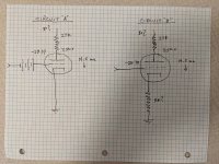
So I'll ask it this way and with a new schematic...
How do I implement "Circuit A" so that all the marked operating points remain by solving for B+?
Secondly how do I convert "Circuit A" into "Circuit B" so all the marked operating points remain by solving for both B+ and Rk?
I hope I've got this question right now. My eTracer loadline calculator gives me Circuit A very easily by entering a resistor and dragging around an operating point and telling me all about the distortion, power, swing etc...
But to actually build it using self bias instead of fixed bias, I need to solve for B+ and Rk.
Circuits "A" and "B"
Also here are the curves and the tube is a 1626 triode:
http://www.r-type.org/pdfs/1626.pdf
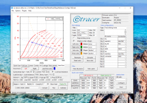
Last edited:
I still do not know about the software you are using.
But . . .
1. Your battery in Circuit A is reversed polarity, from what it should be.
2. Those curves are not triode curves. The tops of them should not curve and fold over to the right.
They may be actual curves, but only if you either have a resistor in the plate, or if you have a resistor in the cathode, or both.
If an actual triode curve, without plate resistor, and without cathode resistor; bent over to the right like that, it would indicate saturation, and would indicate over dissipation and dangerous operation of the tube.
True triode curves are taken with no plate resistor, and no cathode resistor.
True triode curves I am talking about are the ones you would see in a complete tube datasheet.
Tubes that use positive grid voltage are normally designed to be Power RF tubes, not audio tubes; with RF signals typically in Class C, or Class AB2 operation.
Last edited:
I think the curves as measured by eTracer are limited by its power supply. It probably can't supply the higher currents, so the curves are bent to the right.
I still do not know about the software you are using.
But . . .
1. Your battery in Circuit A is reversed polarity, from what it should be.
2. Those curves are not triode curves. The tops of them should not curve and fold over to the right.
They may be actual curves, but only if you either have a resistor in the plate, or if you have a resistor in the cathode, or both.
If an actual triode curve, without plate resistor, and without cathode resistor; bent over to the right like that, it would indicate saturation, and would indicate over dissipation and dangerous operation of the tube.
True triode curves are taken with no plate resistor, and no cathode resistor.
True triode curves I am talking about are the ones you would see in a complete tube datasheet.
Tubes that use positive grid voltage are normally designed to be Power RF tubes, not audio tubes; with RF signals typically in Class C, or Class AB2 operation.
Oops, here is the corrected grid battery
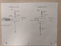
And the curves came from a tube I just scanned, that tube, no resistors, direct from the tracer. The weirdness happens above the max power curve, the tube is actually very linear all below that.
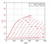
Just scanned now:
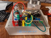
I think the curves as measured by eTracer are limited by its power supply. It probably can't supply the higher currents, so the curves are bent to the right.
Yes that's it, I have the first version of the tracer, the company (one guy) has a mod that increases the max current capability. When I test other triodes this doesnt happen. I'm contacting him today to see how I apply that mod.
Last edited:
For Circuit "B" schematic to be correct, the design grid and plate voltages should be shown referenced to the cathode. Otherwise, they can be taken as referenced to ground. It's a detail, but this way there can be no confusion.
I think the curves as measured by eTracer are limited by its power supply. It probably can't supply the higher currents, so the curves are bent to the right.
For Circuit "B" schematic to be correct, the design grid and plate voltages should be shown referenced to the cathode. Otherwise, they can be taken as referenced to ground. It's a detail, but this way there can be no confusion.
I see because adding an Rk in this context (going from fixed to self bias) and retaining the original operating point, those two voltages now reference to the top of Rk? So when Rk is finally calculated then the plate voltage to ground will be larger but the original operating point was still retained?
Yes that's it, I have the first version of the tracer, the company (one guy) has a mod that increases the max current capability. When I test other triodes this doesnt happen. I'm contacting him today to see how I apply that mod.
Sorry guys for my what seems like my constant stream of mistakes. I just learned that my etracer has a config file update that I didnt apply as I just got a new computer. The give away is that the curves are raised off the 0ma line. The owner is in Taiwan so I need guidance on how to get that config file.
- Home
- Amplifiers
- Tubes / Valves
- Newbie question - algebra to solve for B+ and Rk?
