Picture of Post 35.
What is that tube?
A 45?
A 10Y?
Or what?
all curves in the whole thread are for 1626 tube. post 35 should be disregarded as my machine was not calibrated.
Post 40 has the same tube scanned with the machine calibrated. Curves look better and the curves start at 0ma as opposed to the mis calibrated scan in 35. The tube is very linear below the max power curve. For now I'm disregarding why the sway to the right above the power curve until I talk to some folks at the company.
Last edited:
To get an impression about the graphics:
Wow thanks Joe! I'm going to have to do 10 of these exercises probably for it to become second nature like everyone here, but my work is cut out for me.
The 1626 has a 12.6V filament.
But your graphs show 6.3V filament voltage.
A 1626 with 6.3V on its 12.6V filament will have plate curves that saturate (bend over to the right).
If . . . it works at all.
Are you operating the 1626 at 6.3V?
or at 12.6V?
But your graphs show 6.3V filament voltage.
A 1626 with 6.3V on its 12.6V filament will have plate curves that saturate (bend over to the right).
If . . . it works at all.
Are you operating the 1626 at 6.3V?
or at 12.6V?
Last edited:
The 1626 has a 12.6V filament.
But your graphs show 6.3V filament voltage.
A 1626 with 6.3V on its 12.6V filament will have plate curves that saturate (bend over to the right).
If . . . it works at all.
Are you operating the 1626 at 6.3V?
or at 12.6V?
God I owe you guys so much! Wish I could buy you all steaks and beers. That was it 6A3Summer, here is the new curve, still a very linear tube. All is not lost I guess, we all learned what curves look like when there is not enough emission!

I love it when Physics works!
And, this is a great teaching moment, and a reminder to me too, really look for clues.
Physics always works, but we do not always understand what is going on.
How many times have I made silly mistakes?
Fortunately I am old, so I can not remember most of those times.
And, this is a great teaching moment, and a reminder to me too, really look for clues.
Physics always works, but we do not always understand what is going on.
How many times have I made silly mistakes?
Fortunately I am old, so I can not remember most of those times.
The 1626 has a 12.6V filament.
But your graphs show 6.3V filament voltage.
A 1626 with 6.3V on its 12.6V filament will have plate curves that saturate (bend over to the right).
If . . . it works at all.
Are you operating the 1626 at 6.3V?
or at 12.6V?
I'm glad you're taking my mistakes this way and not fluffing me off with the giggle test 🙂
Now for the same loadline...
Using all the same Ra, ma and Ea we've been discussing 27K, 19.5ma and 250V... The new curves are giving out an even more pleasing 2nd to 3rd harmonic ratio: 1.41% 2nd to only .18% 3rd. I cant wait to hear this as an SE triode, but at a B+ that is under 400V instead of the 800V I'd need here.

Last edited:
You do not need 800V B+.
If you use the 1625 to drive an output transformer that has a 10k primary impedance, and has 1000 Ohms primary DCR, the voltage drop from B+ will be 1000 Ohms times 19.5mA.
That is a 19.5V drop of B+ Volts.
If you use a 27k primary (27k primary is hard to get), that has a 2700 Ohm DCR, that is a 52.65V drop from B+.
You want the primary DCR to be less than 10% of the primary impedance. That is quite lossy, -1db, or 79% power out, versus a lossless transformer.
1 Watt in, 0.79 Watt out.
And, if the primary DCR is 5% of the primary impedance, and if the secondary DCR is 5% of the secondary impedance, the power loss is -1dB. Again, 1 Watt in equals 0.79 Watts out.
I hope that gives you some ideas.
Use your software and tester to find the plate resistance, rp.
If it does not calculate it for you, you have to do it your self.
Take the slope of one of the plate curves, the one that is at the quiescent plate voltage, and quiescent grid voltage.
Measure the slope of that plate curve line (voltage difference versus current difference)
Delta plate voltage/Delta current = rp, the plate resistance.
Try re-running the program, with a plate load that is 3x rp.
See what distortion it reports.
I'm glad you're taking my mistakes this way and not fluffing me off with the giggle test 🙂
Now for the same loadline...
Using all the same Ra, ma and Ea we've been discussing 27K, 19.5ma and 250V... The new curves are giving out an even more pleasing 2nd to 3rd harmonic ratio: 1.41% 2nd to only .18% 3rd. I cant wait to hear this as an SE triode, but at a B+ that is under 400V instead of the 800V I'd need here.
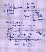
View attachment 922449
This graphics puzzles me. When I take 27k as a plate load resistor I come up with around 47mA Plate current when Vplate is 0V and Vsupply around 800V.
0.0195A x 27,000 = 526.5V drop.
If the 27k is a resistor, the plate will be at a very small voltage.
The software does not tell you how to set up the parameters?
I hope it has a good manual to tell you how to enter the numbers into the software,
and what each Entry Box actually means (like means schematically).
For instance, a 27k primary impedance transformer that has 2.7k DCR.
The voltage drop through 2700 x 0.0195 = 52.65V
That will work in a practical circuit.
27k resistor and 19.5 mA does not work, unless the B+ is high enough to give the plate enough voltage after the resistor drops 526.5V.
250V across the tube, and 526.5V across the resistor = 776.5V
776.5V + 23.5V self bias = 800V B+
".....27k resistor and 19.5 mA does not work, unless the B+ is high enough to give the plate enough voltage after the resistor drops 526.5V.
250V across the tube, and 526.5V across the resistor = 776.5V
776.5V + 23.5V self bias = 800V B+......"
See my post #41
250V across the tube, and 526.5V across the resistor = 776.5V
776.5V + 23.5V self bias = 800V B+......"
See my post #41
The software does not tell you how to set up the parameters?
I hope it has a good manual to tell you how to enter the numbers into the software,
and what each Entry Box actually means (like means schematically).
There are only 5 parameters that can be changed:
1) Quiescent voltage - This moves the operating point left or right
2) Quiescent current - This moves the operating point up or down
3) Load resistance - This changes the angle of the line
4) V out - This changes the "swing" out I guess, it moves the two outer dots on the load line wider or narrower with the operating point in the middle.
5) A checkbox to lock the value of the resistor in place so as not to change the angle of the line if you're dragging a point.
The load line calculator works over the curves you just obtained for that particular tube, in other word there is not a library of curves, you scan the tube then use the loadline calculator over whatever curves you got.
I just recorded a little video of me changing these parameters to see how distortion etc. are computed on the fly. If this helps:
eTracer Load Line - YouTube
Last edited:
Windcrest77,
So it seems that you are getting the results you need from the eTracer.
Is that correct?
Just remember, when you set the eTracer up, in order to calculate the actual B+ you need, you have to calculate the voltage drop of the plate current times the plate load resistor, RL.
And, if you are going to use self bias, you have to calculate the voltage drop of the cathode resistor, RK. Current x RK = self bias (a voltage drop you have to make up by increasing the B+ by that much voltage).
Just add the voltage drops of RL and RK to the 'plate to cathode voltage' to get the B+ that you need.
Or, if you use an output transformer, use the voltage drop due to the DCR of the transformer primary. Plate current x DCR. Add that voltage to the 'plate to cathode voltage' to get the B+ you need.
But the output transformer primary impedance becomes the load line for the tube.
If you use fixed bias, the cathode is at zero volts, so no additional voltage to add (no RK voltage drop).
I hope that covers all you need to know.
Last edited:
Moin Windcrest,
please deal with the basics of electrical engineering first. For example, you have to differentiate between AC and DC. The 27kOhm are the AC specification of the transformer. Power supply is calculated with DC resistance.
Best regards, Frank
please deal with the basics of electrical engineering first. For example, you have to differentiate between AC and DC. The 27kOhm are the AC specification of the transformer. Power supply is calculated with DC resistance.
Best regards, Frank
Windcrest77,
So it seems that you are getting the results you need from the eTracer.
Is that correct?
Just remember, when you set the eTracer up, in order to calculate the actual B+ you need, you have to calculate the voltage drop of the plate current times the plate load resistor, RL.
And, if you are going to use self bias, you have to calculate the voltage drop of the cathode resistor, RK. Current x RK = self bias (a voltage drop you have to make up by increasing the B+ by that much voltage).
Just add the voltage drops of RL and RK to the 'plate to cathode voltage' to get the B+ that you need.
Or, if you use an output transformer, use the voltage drop due to the DCR of the transformer primary. Plate current x DCR. Add that voltage to the 'plate to cathode voltage' to get the B+ you need.
But the output transformer primary impedance becomes the load line for the tube.
If you use fixed bias, the cathode is at zero volts, so no additional voltage to add (no RK voltage drop).
I hope that covers all you need to know.
Yes this helps a lot, I was wondering (dreading) about the load when it became a Transformer instead of a resistor, now I have something to go on for that as you mentioned it first here. So with the AC current the inductance of the OPT becomes the "big" load and so you use use the DCR for the B+ and Rk DC set point comeback we've been discussing. And when cascading stages I see how the next stage load goes in parallel with the previous stage load but the coupling capacitor makes that the AC load line and steeper because the resistances go in parallel.
Learning how to determine actual part values and a power supply from a random chosen operating point... I knew was the basic key needed to move on from mere kit building but couldn't begin to get there.
This wont sink in until I've done this exercise several times. But to everyone here thanks a lot.
Another thing to look out for, is what output transformers are available. Often, you are limited to what is available, unless you wind your own. For example, can you get an output transformer that will give you your design loading.
Hopefully, the transformer primary inductance is not a significant part of the primary impedance, except at low frequencies.
With a 10k primary, and 1k secondary, with a 1k total secondary load, At mid frequencies, the transformer primary is 10k.
At some low frequency, where the inductive reactance = 10k, you have 10k inductive reactance in parallel with 10k reflected impedance due to the secondary load of 1k. At that frequency, the primary impedance is 7.07k.
That is the -3dB low frequency point of that amplifier. That causes low frequency roll off,
6 dB/Octave for frequencies below that.
At some high frequency, distributed capacitance of the primary, may become a factor.
The capacitive reactance is in parallel with the 10k reflected load (again, with 1k on the secondary).
Also, there is not perfect coupling from the primary to secondary at high frequencies.
That is the leakage reactance.
The combination of distributed capacitance, and leakage reactance causes high frequency roll off,
typically 12dB/Octave above the -3dB high frequency bandwidth.
Find some good text books, and start learning about electronics. It can serve you well.
Last edited:
- Home
- Amplifiers
- Tubes / Valves
- Newbie question - algebra to solve for B+ and Rk?