Sorry, think I misread your post.
The intention with the attunation before the amp is to use the amp at 30dB gain , but have the 26dB total gain of attunator and amp.
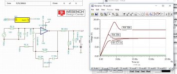
Tried in Tina-TI, but needed 15k R1 and 22k R2 to get to 26dB total.
Then the johnson noise form R1 may be to high?
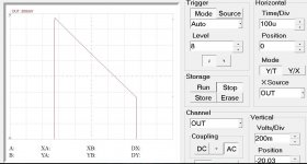
I also see that high input impedance alter the phase at high frequency, so that was a lesson learned. See picture with 1k R1 and 15k R1.
I have played around with Rf 20k, R3 1k and R1 1k. The square wave look stellar up to 600nf straight to ground on the output after the 0.15ohm.
So I would go for that solution
The intention with the attunation before the amp is to use the amp at 30dB gain , but have the 26dB total gain of attunator and amp.
Tried in Tina-TI, but needed 15k R1 and 22k R2 to get to 26dB total.
Then the johnson noise form R1 may be to high?
I also see that high input impedance alter the phase at high frequency, so that was a lesson learned. See picture with 1k R1 and 15k R1.
I have played around with Rf 20k, R3 1k and R1 1k. The square wave look stellar up to 600nf straight to ground on the output after the 0.15ohm.
So I would go for that solution
Attachments

Then the johnson noise form R1 may be to high?
And here's your solution.
Through Hole Resistors | Resistors | DigiKey
http://www.vishay.com/docs/31018/cmfind.pdf
Super stable, super high bandwidth, super low noise. I buy ten at a time and keep a collection of values on hand. You can use significantly higher resistor values without introducing excessive noise with these resistors.
With the emphasis on "excess". There is no way around plain ol' thermal (Johnson) noise, obviously, which is a function of resistor value and resistor value only. Thought I'd better clarify before anyone thinks there's some sort of magic involved.
Obtaining low values of attenuation passively can be quite annoying. I'd think about an inverting opamp input stage plus using the '3886 in inverting mode, which ought to give marginally better performance anyway. It's not necessarily any better for noise, but that should be largely a non-issue at this point anyway - power amp noise tends to be swamped by preamp noise more often than not. With noise data for a 5532 and 22k/15k resistors I'm getting 3.48 µV, so plus 30 dB that's about 105 µV plus power amp noise. It generally takes a rather low-noise preamp to get down there (NJM2068 or LM4562 class opamp plus lowish-impedance feedback network).
Obtaining low values of attenuation passively can be quite annoying. I'd think about an inverting opamp input stage plus using the '3886 in inverting mode, which ought to give marginally better performance anyway. It's not necessarily any better for noise, but that should be largely a non-issue at this point anyway - power amp noise tends to be swamped by preamp noise more often than not. With noise data for a 5532 and 22k/15k resistors I'm getting 3.48 µV, so plus 30 dB that's about 105 µV plus power amp noise. It generally takes a rather low-noise preamp to get down there (NJM2068 or LM4562 class opamp plus lowish-impedance feedback network).
Last edited:
With the emphasis on "excess". There is no way around plain ol' thermal (Johnson) noise, obviously, which is a function of resistor value and resistor value only. Thought I'd better clarify before anyone thinks there's some sort of magic involved.
This is something they didn't teach us about. (They didn't teach us a lot of stuff in the 70s when I went to school. I always had a thousand annoying questions that all had the same answer: "Wait until grad school." Bastards.)
Vishay claims "Exeptionally low noise: typical 0.1 uV/V." Is there a tutorial that could clarify this issue for me? It's directly relevant to the stuff I'm doing now. Thanks.
lowish-impedance feedback network
I always go for the lowest values that are practical.
http://www.analog.com/media/en/training-seminars/tutorials/MT-047.pdf
From analog is straight to the point on johnson noise
From analog is straight to the point on johnson noise
Yes, thank you very much.
I did look up Johnson noise, and I realized that they did in fact teach us about it. (Even a wire has Johnson noise I remember now.) They also kind of glossed over it with the assumption (I guess) that it won't be very useful information.
There are other types of noise that I need to learn more about. I've been building line level circuitry using basic rules of thumb and I have obtained excellent results. I know that smaller resistors = less noise (and offset voltage) and I know that fancy pants resistors can help with noise (and precision and stability too) in many circuits. I'm lazy and do seat of the pants calculations and follow up with tweaks based on measurements. It works but I want to do better.
They taught us so much and most people use so little in their line of work. It's been decades and you know what they say about use it or lose it. I'm going to do some refresher study.
Available thermal noise power from a resistor actually is always the same, namely 4kTΔf. R only determines, guess what, the ratio of voltage noise (seen unloaded) to current noise (going into a short). We mostly care about voltage noise because our circuitry tends to have high-impedance (voltage) inputs.
I actually have a little noise calculator for opamp circuits online. Something like this tends to be quite handy.
A spec like "0.1 uV/V" quite clearly refers to excess noise, the kind that occurs when current flows through a resistor (and Ohm's law is telling us what sort of current corresponds to 1 V). Wikipedia has more to say on this. So apparently this actually is given in µV/V/decade, and a value of 0.1 or -20 dB puts us in "rather decently low-noise" territory.
Anyway, in audio we can pretty much just use metal film or thin-film resistors and be done with it. The effects that are bothering instrumentation folks in cheap MFs (like thermoelectric effect due to steel end caps and wires) are generally irrelevant here, and linearity already is pretty good as-is. There is nothing keeping you from using fancy bulk metal foil resistors, but I wouldn't expect any measurable performance difference until you get to very high-spec circuitry.
Last edited:
I actually have a little noise calculator for opamp circuits online. Something like this tends to be quite handy.
Oh that's wonderful. But you're enabling my sloth! Someone with my edumacation should be able to figure that out from scratch.
A spec like "0.1 uV/V" quite clearly refers to excess noise, the kind that occurs when current flows through a resistor (and Ohm's law is telling us what sort of current corresponds to 1 V). Wikipedia has more to say on this. So apparently this actually is given in µV/V/decade, and a value of 0.1 or -20 dB puts us in "rather decently low-noise" territory.
Very informative; especially this subtle point
Using a larger value of resistance produces a larger voltage noise, whereas a smaller value of resistance generates more current noise, at a given temperature.
Anyway, in audio we can pretty much just use metal film or thin-film resistors and be done with it.
Great rule of thumb. It makes it a lot easier to "design" a practical circuit.
So thanks!
> They also kind of glossed over it ... won't be very useful information.
If your project is not spoiled by hiss, you don't care a bit.
If you are paid to hiss-reduce, you will (or should) learn a lot about the topic. The number of expert practitioners in each field (audio, radio, instrumentation) may be in the dozens. Not for "all" EE students.
Nah, I don't remember much about hiss in 1970s undergrad EE.
Logic, power electronics, even high-level audio, are not bothered by hiss. (I'm not sure why we care in a high-level Chip-Amp?? 30dB, 26db; it is all overwhelmed by mike or phono hiss pre-amped 40+ dB.)
> They also kind of glossed over it ... won't be very useful information.
If your project is not spoiled by hiss, you don't care a bit.
My stuff works great. No hiss etc. It's just a topic of interest.
If you are paid to hiss-reduce, you will (or should) learn a lot about the topic. The number of expert practitioners in each field (audio, radio, instrumentation) may be in the dozens. Not for "all" EE students.
Ha! I only get a little freelance work from DJ's. There's plenty of ambient noise at nightclubs and festivals.
Last cool thing I did was a custom state variable filter for a DJ that was trying to emulate a very popular DJ's style. I saw him jacking around with the equalizer and mucking up the sound and he showed me a video of this DJ from New York (Frankie from New York; recently deceased). I knew right away what he needed.
Most of my effort is geared towards trying to get DJs to understand power factor and how it relates to tone control use. This seems to be hard for them to grasp; they always overboost the bass. My mantra is always "cut don't boost." I also try to get them to understand how dreadful equalizers are when you overuse them. All they care about is music. I want to help them so they can be as cool as the big guys like Frankie.
As far as "experts" are concerned, I was always told that I could NEVER be an audio engineer by my teachers and counselors. And I never made any money to speak of doing it. I didn't do engineering for most of my career (big mistake it turns out because now I can't even get any type of engineering job and my old industry is kaput) and when I did it was geared towards high energy power for manufacturing facilities.
Logic, power electronics, even high-level audio, are not bothered by hiss. (I'm not sure why we care in a high-level Chip-Amp?? 30dB, 26db; it is all overwhelmed by mike or phono hiss pre-amped 40+ dB.)
I know.
From post#1
My understanding was that if you need to change gain from 30,5dB to 26dB your attention to detail is high 🙂
Now, I know that for my speaker load, I've been explained in clear terms that I need to change the gain, to 26dB.
Thanks
My understanding was that if you need to change gain from 30,5dB to 26dB your attention to detail is high 🙂
torgeirs:
If I recall correctly, the person helping me with my project said it was to keep the amps in SoA under lower impedance loads. Also, the Chipamp.com is more like 33.5dB or something in that ballpark, isn't it?
I'm likely to use the values that Siegfried Linkwitz uses-I think he knows what he's doing.
If I understand correctly, Siegfried's circuit for LM3886 is very similar, except he uses 19.6k and 1k resistors. So shouldn't I just be able to swap in those two values and get what I'm looking for?
Thanks
Yes, 20k and 1k should do it. If it is good enough for Linkwitz...🙂
If your speakers has large capasitive phase angles I would consider a 20k in series with a 50p cap in parallell with the 20 k. (As recomended by TI)
If your speakers has large capasitive phase angles I would consider a 20k in series with a 50p cap in parallell with the 20 k. (As recomended by TI)
Last edited:
torgeirs:
If I recall correctly, the person helping me with my project said it was to keep the amps in SoA under lower impedance loads. Also, the Chipamp.com is more like 33.5dB or something in that ballpark, isn't it?
Thanks
Not sure how amplifier gain helps/hinders SOA. Please explain, I'm curious.
That's good advice.you could start with 27k & 1k
Without Part CC present and at least 180, the outputs will probably oscillate (bad tone) when the amp is working hard. The datasheet mentions it.Well... at least until the Cc cap comes into play.
Thanks for that. That advice makes sense, but doesn't match what I asked for. 1 + 27/1 still equals 28, not 26. Is there no easy way to do this and get exactly 26 gain?
Thanks
Thanks
Thanks for that. That advice makes sense, but doesn't match what I asked for. 1 + 27/1
still equals 28, not 26. Is there no easy way to do this and get exactly 26 gain?
A gain of 26dB is a factor of 20 times. Then 20 = ( 1 + R / 1k ).
So R = 19k. A standard value is 19.1k, only half a percent off.
OK, just came back to this now. So, I need to change only the one resistor, then? I was told that standard design practice was to make Rf=R2 in this type of design. Is that recommended here?
BTW, the schematic is not exactly the same as the PCBs. On the schematic, "S1" is showed for a switch. There are no facilities on the board for a switch, AFAICT.
BTW, the schematic is not exactly the same as the PCBs. On the schematic, "S1" is showed for a switch. There are no facilities on the board for a switch, AFAICT.
Last edited:
- Status
- Not open for further replies.
- Home
- Amplifiers
- Chip Amps
- Newbie question about gain resistors