the difference between correctly amplified fast transient content and the exaggerated amplification of HF, that happens when severe overshoot is resulting from the lower stability margins (inadequate compensation) is very audible.
Yes, and you can hear 10% distortion, but will there be severe overshoot in normal cases going from 30dB to 26dB? Or will the chipamp implementation always suffer from severe overshoot? With normal speakers or ribbon speakers?
The reason I ask is that many on this forum think the unmodded XY and Chipamp sound as god as any other amps at everyday listening levels.
(Pressed to to the max the artifacts will starting to show, i guess)
The reason I ask is that many on this forum think the unmodded XY and Chipamp sound as god as any other amps at everyday listening levels.
(Pressed to to the max the artifacts will starting to show, i guess)
I guess you need extensive listening experience with same high quality drivers and room to hear subtle changes in transient response of the amp. Do not doubt you have that, but you are one of the few lucky ones.
Any competent person that's worked with sound reinforcement for decades ought to be able to hear something. And believe me, I'm not the only one.
It's like singing. Do you think that those opera singers were born with their abilities? They make singing sound effortless, but you try it. It takes lots of practice and study. I was told for 50years that I can't sing a note. Then one day a musician sat down with me at a piano and showed me some stuff. I practiced what he showed me for a while, and guess what - now I can sing over a 2 1/2 octave range! I'm the karaoke king- people that have known me my whole life can't believe it. I'm not really gifted, and I don't spend a lot of time honing my newly found skill. But the point is that I went from clueless to competent - just by applying myself.
Think we agree that a trained ear can hear more nuances than an untrained ear.
But there is a limit where the mecanics of the ear and the prosessing of the brain is not good enough to detect a differense. I state that changing gain from 30 dB to 26dB is near that limit of what is possible to detect.
At least it conserns so few that it can be ignored in this kind of diy kit.
But there is a limit where the mecanics of the ear and the prosessing of the brain is not good enough to detect a differense. I state that changing gain from 30 dB to 26dB is near that limit of what is possible to detect.
At least it conserns so few that it can be ignored in this kind of diy kit.
I state that changing gain from 30 dB to 26dB is near that limit of what is possible to detect.
.
You're missing the whole point.
Changing gain changes loop gain. Changing loop gain changes transient response. At some point this becomes a significant factor. With chip amps there is a small window of gains where the performance will be acceptable. Go too low, the chip becomes unstable. Go too high, and the loop gain gets so low that distortion increases.
Look at the Bode plot in the datasheet. It tells the whole story.
I'm not sure anyone is missing any point. You're just asked to define and justify the point at which "this become a significant factor" and the boundaries of that "small window of gains". Is a gain of 26dB outside that window and by which criteria ?
Here's what the Bode plot says:
At 20dB, the phase margin is about 65°.
At 26dB, about 77°.
At 30dB, about 85°.
Well... at least until the Cc cap comes into play.
Here's what the Bode plot says:
At 20dB, the phase margin is about 65°.
At 26dB, about 77°.
At 30dB, about 85°.
Well... at least until the Cc cap comes into play.
I'm not sure anyone is missing any point. You're just asked to define and justify the point at which "this become a significant factor" and the boundaries of that "small window of gains".
I'm just trying to get our friend to think about the factors in play.
Is a gain of 26dB outside that window and by which criteria ?
No, it's right in the "sweet spot." But I'm trying to get our friend to figure this out on their own.
Here's what the Bode plot says:
At 20dB, the phase margin is about 65°.
At 26dB, about 77°.
At 30dB, about 85°.
Well... at least until the Cc cap comes into play
I'm trying to get our friend to realize the usefulness of this information.
20° is a lot. Add on a bit of capacitance to subtract say 30° from those basic resistive load values and you end up with
+20dB, 35°
+26dB, 47°
+30dB, 55°
Exaggerated transients and sibilance will have become very noticeable.
+20dB, 35°
+26dB, 47°
+30dB, 55°
Exaggerated transients and sibilance will have become very noticeable.
Well the original question was 26dB so 8 degrees is more correct, but I thought you had to shift the phase curve with the gain to see the margin? (I haven't studied it for a while so I might be wrong)
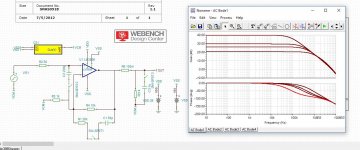
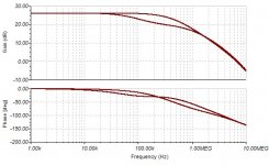
I enclose the TINA-TI files for the analysis i have done. And can't see that much of a difference.
The picture is 20dB, 26dB, 30dB and 40dB gain with phase. No compensation.
Phase of 40 dB is the red lower.
Put in a picture of 20k, 50p compensation also.
Well at least it is one of the cheapest audiotest you can do to switch between 20k and 30k and listen to differences. Just remember to scale the output down 4 dB for 20k.
Attachments
Last edited:
So (and no doubt someone will label me ungrateful here), there seems to be almost no consensus about how I should do this, or even which resistors to change? I've seen a bunch of different answers, and then it devolved into an argument about something completely different.
So (and no doubt someone will label me ungrateful here), there seems to be almost no consensus
about how I should do this, or even which resistors to change? I've seen a bunch of different
answers, and then it devolved into an argument about something completely different.
Welcome to diyAudio.
Measure the overshoot on your scope view.Well the original question was 26dB so 8 degrees is more correct, but I thought you had to shift the phase curve with the gain to see the margin? (I haven't studied it for a while so I might be wrong)
I enclose the TINA-TI files for the analysis i have done. And can't see that much of a difference.
The picture is 20dB, 26dB, 30dB and 40dB gain with phase. No compensation.
Phase of 40 dB is the red lower.
Put in a picture of 20k, 50p compensation also.
Well at least it is one of the cheapest audiotest you can do to switch between 20k and 30k and listen to differences. Just remember to scale the output down 4 dB for 20k.
Change the capacitance at the load and see the overshoot change.
Change the stage gain and see the overshoot change.
No overshoot and near square corners on your 1kHz squarewave test signal indicates that the amplifier is scaling the input signal to become the output signal. Overshoot indicates an exaggeration of the fast transients.
Your question was answered.So (and no doubt someone will label me ungrateful here), there seems to be almost no consensus about how I should do this, or even which resistors to change? I've seen a bunch of different answers, and then it devolved into an argument about something completely different.
Don't you remember you posted:
Thanks for all that info,
Last edited:
Gain = 1+ Rf/R3
Rf = 20k
R3 = 1k
Gives about 26dB gain
You can also keep the original 33dB gain and devide your signal amplitude with a voltage devider of two identical resistors before the amp input to get 33dB - 6dB = 27 dB gain
Then both camps here may be satisfied with the answer🙂
Rf = 20k
R3 = 1k
Gives about 26dB gain
You can also keep the original 33dB gain and devide your signal amplitude with a voltage devider of two identical resistors before the amp input to get 33dB - 6dB = 27 dB gain
Then both camps here may be satisfied with the answer🙂
About the square wave. Tomchr's xy measurements shows quite heavy capasitiv loading before ringing. Tried on the simulator but the ringing was so small i could not see it
Applying attenuation of the input signal does not change the gain of the amplifier.Gain = 1+ Rf/R3
Rf = 20k
R3 = 1k
Gives about 26dB gain
You can also keep the original 33dB gain and devide your signal amplitude with a voltage devider of two identical resistors before the amp input to get 33dB - 6dB = 27 dB gain
Then both camps here may be satisfied with the answer🙂
You posted:
note, there are no terms in there to cover input attenuation ratios.Gain = 1+ Rf/R3
That is not amplifier gain.
You can laugh as much as you like, adding attenuation of the input signal does not alter the amplifier gain.
You can laugh as much as you like, adding attenuation of the input signal does not alter the amplifier gain.
Are you saying the phase margin is altered with a voltage devider before the amp? This is a noninverting amp.
By the way the gain of the amp is 30,5 dB so 6 dB is a bit much. Lets say R1 = 10k and keep R2 = 22k
I'm talking about changing values of R1 and R2 in:

By the way the gain of the amp is 30,5 dB so 6 dB is a bit much. Lets say R1 = 10k and keep R2 = 22k
I'm talking about changing values of R1 and R2 in:
Last edited:
- Status
- Not open for further replies.
- Home
- Amplifiers
- Chip Amps
- Newbie question about gain resistors