Whose board is that?
After Chad production boards arrived I became even more spoiled. I won't accept anything less than 2 oz, double face with ultra wide traces, vias and all the trimmings! 😉
After Chad production boards arrived I became even more spoiled. I won't accept anything less than 2 oz, double face with ultra wide traces, vias and all the trimmings! 😉
Grataku,grataku said:Whose board is that?
This would be a second mass Aleph board purchase for Dale (harvardian). It will be based on BrianGT’s latest design.
http://www.diyaudio.com/forums/showthread.php?s=&threadid=6104
Rodd Yamashita
Output boards:
If we can get to 100 output boards, the price will be <$5.00 ea.
I am going to make the traces on these boards wider and make sure that the resistor spacing is perfect for the RN60/RS5 resistors.
Best Regards,
Dale
If we can get to 100 output boards, the price will be <$5.00 ea.
I am going to make the traces on these boards wider and make sure that the resistor spacing is perfect for the RN60/RS5 resistors.
Best Regards,
Dale
Hi Steve et all,
The boards will be at cost which will be ~$10 - $12 ea. (plus actual shipping)
May be less if we get enough interest.
Best Regards,
Dale
The boards will be at cost which will be ~$10 - $12 ea. (plus actual shipping)
May be less if we get enough interest.
Best Regards,
Dale
Dale if you fatten up them traces on both the output and the driver boards I may buy a couple for the cold days! 😉
which boards
are these the driver boards? i.e. they hold the big mosfets?
I would think so but the link you pointed to was slightly ambiguous with the description. Also I'd assume that you need to order two per channel, no? in that case I'd be in for four. more if the price goes down.
are these the driver boards? i.e. they hold the big mosfets?
I would think so but the link you pointed to was slightly ambiguous with the description. Also I'd assume that you need to order two per channel, no? in that case I'd be in for four. more if the price goes down.
Hello,
Sorry about any confusion:
There will be two boards available.
1) Aleph driver board using BrianGT latest layout. These will be done as a high quality single sided board with top silkscreen and soldermask. They will have 2.5Oz copper (thick) The estimated cost is ~9.00 per board.
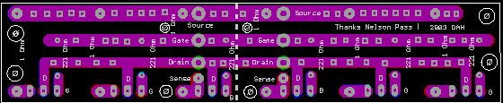
2) Output board. These boards have space for 6 TO247 fets, the 221 Ohm gate resistors, and the 1 Ohm high wattage resistors. They have two sets of connections, so that you can cut them in half for lower powered Alephs. These will also have 2.5Oz copper and be single sided. I will widen the traces from the previous version. Estimated cost is < $5.00 per board.
Shipping will also be at cost.
Hope this clarifies things a bit. Sorry for the confusion.
Best Regards,
Dale

Sorry about any confusion:
There will be two boards available.
1) Aleph driver board using BrianGT latest layout. These will be done as a high quality single sided board with top silkscreen and soldermask. They will have 2.5Oz copper (thick) The estimated cost is ~9.00 per board.
2) Output board. These boards have space for 6 TO247 fets, the 221 Ohm gate resistors, and the 1 Ohm high wattage resistors. They have two sets of connections, so that you can cut them in half for lower powered Alephs. These will also have 2.5Oz copper and be single sided. I will widen the traces from the previous version. Estimated cost is < $5.00 per board.
Shipping will also be at cost.
Hope this clarifies things a bit. Sorry for the confusion.
Best Regards,
Dale
Hi,
I'm have a question about the output boards
What is the size of these boards?
The reason is that I'm looking for output-boards where each fet is 3cm seperated from each other.
Preview: My project
If you look closely you see the copper-plates with pre-drilled holes, where the fets should be placed.
I ordered 2 driver boards ($9 per each) = $18+shipping
If the output boards are too big, I'll go for silver-wiring p2p connections.
Remco.
Looking foreword to getting more boards and building my Sister a pair of these wonderful amps......Still have lots of semis here!
Would it be possible to space the pads for Q-4, and Q-5 a bit , say on a triangle???? The originals were a wee bit tight for soldering and one of them caused me to loose a couple of outputs and R-15 on the powerup of the first amp. I actually ended up cutting the middle foil away on both PCB's, drilling the hole for the base farther out and soldering the base a bit off center of the other two holes. You may be able to tell in the photo above what I did..........
Just let me know when you need payment.......Also, how much more for gold plating?
Blank, I did PTP silver teflon wiring on my 2's and it works out well. You can see some of how I did it in the photo of the driver board above. Doesn't take that long to do with turrett terminals, and its also very sturdy. Both outer heatsinks connect to the center one and then to the pcb. This way all leads are the same length within reason.....
Thanks,
Mark
Mark A. Gulbrandsen said:Looking foreword to getting more boards and building my Sister a pair of these wonderful amps......Still have lots of semis here!
Would it be possible to space the pads for Q-4, and Q-5 a bit , say on a triangle???? The originals were a wee bit tight for soldering and one of them caused me to loose a couple of outputs and R-15 on the powerup of the first amp. I actually ended up cutting the middle foil away on both PCB's, drilling the hole for the base farther out and soldering the base a bit off center of the other two holes. You may be able to tell in the photo above what I did..........
Just let me know when you need payment.......Also, how much more for gold plating?
Mark, the boards that I sent you were from the first board order. The newer boards are revised to have better layouts for Q4 and Q5. Sorry for the mistake on the first version. Here is a picture of the latest version. I learned a lesson about using default footprints in layout software:
--
Brian
Attachments
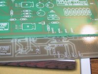
Looks good Brian!! That should do the trick. Man, you should hear these amps. Amazing!
Also, Say hi to Norm and Oscar at Smart Devices for me next time you see them. I've been using Norm's stuff for over 20 years. Will also be switching to their toroids next time around as well.
Regards,
Mark
Also, Say hi to Norm and Oscar at Smart Devices for me next time you see them. I've been using Norm's stuff for over 20 years. Will also be switching to their toroids next time around as well.
Regards,
Mark
Here is the new output board. I almost doubled the trace widths, made the hole sizes for the wires and 5W resistor bigger, made the traces on both sides of the board and put vias through for heat conduction.
The boards will be double sided, with top silkscreen. There will be no soldermask as this retards heat and lowers the current rating for the traces. The copper will be reflowed with tin, so there should be no oxidation.
We are up to 77 driver boards and 189 outputs.
Looks like I will place an order for 100 drivers and 250 outputs.
Should I wait another couple of days?
Dale
Attachments
Dale,
If you want to make any modifications to the main boards, I can send you the protel layout files.
--
Brian
If you want to make any modifications to the main boards, I can send you the protel layout files.
--
Brian
Brian,
I didn't get any feedback from the second version for suggested changes. They must have been perfect!
I did change the ouput boards and will make them double sided since it may make soldering easier and will provide for more current flow.
Does anyone have any suggestions?
Dale
I didn't get any feedback from the second version for suggested changes. They must have been perfect!
I did change the ouput boards and will make them double sided since it may make soldering easier and will provide for more current flow.
Does anyone have any suggestions?
Dale
- Status
- Not open for further replies.
- Home
- Amplifiers
- Pass Labs
- New wiki for Aleph2 Group buy