Thanks Koonw!
I also thought on the same....🙂
What kind of diode do you suggest for D5-10?
Greets:
Tyimo
I also thought on the same....🙂
What kind of diode do you suggest for D5-10?
Greets:
Tyimo
Last edited:
Thanks Koonw!
I also thought on the same....🙂
What kind of diode do you suggest for D5-10?
Greets:
Tyimo
UF4007
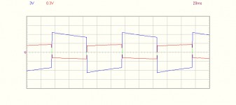
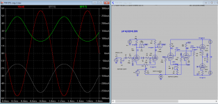
This is what I get with 3 separated PSU+ccs at 8 ohms dummy load.
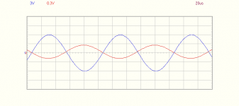
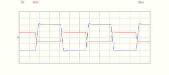
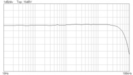
Captures are: 1k/2w; 10Hz/2w; 10k/2w; 10Hz-60K at 1dB/div 2w
Captures are: 1k/2w; 10Hz/2w; 10k/2w; 10Hz-60K at 1dB/div 2w
Attachments
Last edited:
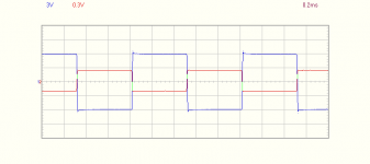
Attached is sim of possible bias, HT voltage and current variation under heavy load and idle condition. In my own amp the PSU dropped from 170V to 140V at full power both channel on. The bias drop from -58 to -51, about 20W each. DC offset is not a problem at full load.
Attachments
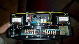
Hey guys, what transformer(s) are you using for the 6C33C heaters?
I'm using this one in the link, but it may not be available in the US: | 2 Output Toroidal Transformer, 225VA, 2 x 12V ac |
Last edited:
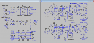
I'm trying to remember my tube theory and wondering if the 6C33Cs here are operating in Class A push pull, Class B or Class AB.
I'm trying to remember my tube theory and wondering if the 6C33Cs here are operating in Class A push pull, Class B or Class AB.
@about -50V bias
Class A 0-100mW
Class AB 100mW & above
@20W it's approaching pure Class B. But if you bias @-80V, it'll be Class AB to B nearly all the way with very tiny Class A portion, maybe under 1mW.
Last edited:
@about -50V bias
Class A 0-100mW
Class AB 100mW & above
@20W it's approaching pure Class B. But if you bias @-80V, it'll be Class AB to B nearly all the way with very tiny Class A portion, maybe under 1mW.
But in my case, as I intend 32 ohms, shell I rich class A ? What bias shall be?
But in my case, as I intend 32 ohms, shell I rich class A ? What bias shall be?
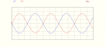
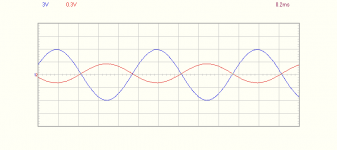
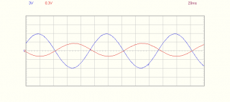
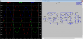
Yes, as you will get higher output voltage with same amount of current in Class A, as the power (V*V/32) is more when load is 32 ohms, est about 0.5W, See attached, 4*4/32=0.5W. Of course as waveform shown some asymmetry, if in actual Class A it would have 10% distortion, we can't really define a clear line when it's going Class AB. But the higher the load, the larger Class A portion will be I agreed. I don't think lowering the bias will help much due to heat, unless you can handle it. If you bias -35V, the current is about 500mA(Dissp=75W), you get 1W Class A into 32 ohms. Maybe you can try -40 to -45V.
Edit: You maybe able to increase Class A portion if you increase the cathode res. of 6C33c, say 3-5 ohms, maybe 3-4W into 32 ohms.
Attachments
Last edited:
Yes, as you will get higher output voltage with same amount of current in Class A, as the power (V*V/32) is more when load is 32 ohms, est about 0.5W, See attached, 4*4/32=0.5W. Of course as waveform shown some asymmetry, if in actual Class A it would have 10% distortion, we can't really define a clear line when it's going Class AB. But the higher the load, the larger Class A portion will be I agreed. I don't think lowering the bias will help much due to heat, unless you can handle it. If you bias -35V, the current is about 500mA(Dissp=75W), you get 1W Class A into 32 ohms. Maybe you can try -40 to -45V.
You are right, thanks. I wonder if I'll get better sound in reality. For now I have to fix several steps till the moment when I'll swich the esl 63 on 32 ohms. I am still listening diffrent kind of ecc83 and ef86......the best sounding ecc83 were Philips Miniwatt and ef86 mullard, but I shall try some Telefunken to compleat that test.
You are right, thanks. I wonder if I'll get better sound in reality. For now I have to fix several steps till the moment when I'll swich the esl 63 on 32 ohms. I am still listening diffrent kind of ecc83 and ef86......the best sounding ecc83 were Philips Miniwatt and ef86 mullard, but I shall try some Telefunken to compleat that test.
You'll hear the sound becomes thicker and warmer. But you may get the same effect if you increase the current of ecc83 of 1st LTP, say from current 0.5mA to 1mA, I definitely hear the difference. If you adjust 1st LTP, you need to adjust 2nd LTP to re-bias correctly, not a big issue.
Last edited:
You'll hear the sound becomes thicker and warmer. But you may get the same effect if you increase the current of ecc83 of 1st LPT, say from current 0.5mA to 1mA, I definely hear the difference. If you adjust 1st LPT, you need to adjust 2nd LPT to re-bias correctly, not a big issue.
Interesting, I shall try this.
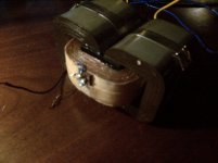
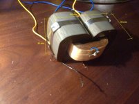
By the way, Your sim program can simulate the behaviour of my esl 63 especialy around the primary of the input transformers? see the attech
In case trafo specs are needed, Rprim =0,65 ohms and L= 360 mH
Attachments
Last edited:
Interesting, I shall try this.
By the way, Your sim program can simulate the behaviour of my esl 63 especialy around the primary of the input transformers? see the attech
In case trafo specs are needed, Rprim =0,65 ohms and L= 360 mH
LTSpice use inductance for transformer simulation. So Lpri=360mH, Lsec will have to be calculated from impedance ratio or inductance ratio. So I assume L14 and L15 both are same, 8 ohms to 2k transformer, and so Lsec inductance is 90H (0.36*2000/8), is it correct?
Edit: sorry 16 to 2K transformer. I recalculated as 45H
Last edited:
LTSpice use inductance for transformer simulation. So Lpri=360mH, Lsec will have to be calculated from impedance ratio or inductance ratio. So I assume L14 and L15 both are same, 8 ohms to 2k transformer, and so Lsec inductance is 90H (0.36*2000/8), is it correct?
I'll chek latter all again and I shall be back with .
All I know for shure about the trafos is the prim/sec ratio 1/125 and the Resistence of each one 0,65 Ohms. I have to chek inductance again as I am not shure if 360mH was with sec shorted or not. L14 and L15 are the same but 8 ohms are achived with paralel linked so I asume each of them has 16 ohms.
Attachments
I'll chek latter all again and I shall be back with .
All I know for shure about the trafos is the prim/sec ratio 1/125 and the Resistence of each one 0,65 Ohms. I have to chek inductance again as I am not shure if 360mH was with sec shorted or not. L14 and L15 are the same but 8 ohms are achived with paralel linked so I asume each of them has 16 ohms.
If the turn ratio is 125 and Lsec is 0.36, then the impedance ratio =125*125=15625, and Lpri=15625*0.36=5625H or Pri/Sec=250K/16 (250K/16=15625). You can get 6.5kV at full power with input of 2V-p.
I can sim another if you confirm the actual value.
Attachments
Last edited:
If the turn ratio is 125 and Lsec is 0.36, then the impedance ratio =125*125=15625, and Lpri=15625*0.36=5625H or Pri/Sec=250K/16 (250K/16=15625). You can get 6.5kV at full power with input of 2V-p.
I can sim another if you confirm the actual value.
I have allready compleat measuring with digital bridge.
Prim is 0,5 ohms 36 mH 46 winds
Sec is 3,1L 450 H 5600 winds (26pF)
Can you trace 10hz -100Khz at 2w and full power 8 & 32 ohms ?
Also has to be counted the esl imput network R15/C25 and R1, R2
- Home
- Amplifiers
- Tubes / Valves
- New Tim Mellows OTL project