>using the PLL to generate the lead / lag signal.
Oh yes, PLL control as well!
A PLL's lock range is quite limited and it is necessary to use velocity (RPM) detection to bring the PLL into lock range first, THEN do phase locking.
That AN5675 Ic used by the 1210 is pretty much a clone of the discrete circuitry used in the Sp10.
The major difference that I'm proposing is to vary the exciter oscillator signal, rather than try to adjust or vary the 3 phase coil signals. This means only one VCA instead of 3, and no need to control the symmetry / balance of 3 independant amplifiers.
The phase comparator method I have not decided on. Method-1 would be to use a ramp generator and sample-hold (as done in the original SP10).
Method-2 would be a digital method, using a phase-to-PWM converter (quite simple with one RS-latch and a D-flip-flop).
I guess I'll make one of each and see what works.
Theres also going to be a problem measuring the overall performance - the sorts of wow/flutter figures quoted by the best TT manufacturers are very low, and measuring a consistent improvement might be tricky.
I'm still interested to know what peoples problems are with the original SP10 electronics - WHY do you want to replace them?
I think one of the main reasons for an updated power supply/controller is aging/dated electronics..
Also, if you could isolate the motor from the controller, it would make it much easier to mount in a custom plinth, and I'm sure would add to it's sonic potential
Speed control ( .1% increments) would also be very nice..
Here are some of the very first posts of this thread that state what is wanted...
Shaun
Post #2
Yikes!! No takers?
OK, let's start:
1. Start/stop button (single or separate?)
2. Variable speed dial/slider (variable by what %age?)
3. Four user-presetable speed buttons
4. Reverse function (could be dangerous!)
5. Electronic Brake for stop function
6. Hold/ free platter when stopped.
Questions:
Should the controller (or a version of the controller) use the existing on-board controls or be self-contained?
Should it use own power supply or the existing unit?
__________________
Shaun Onverwacht
_____________
Post #3
Hello Shaun,
Have you started on this project? I know that if you take this to other forums (vinyl asylum for example) you would get much more attention.
I for one would love to be able to have "
1.) a modern power supply
2.) speed control (at least within 0.1% increments, and with knob not slider)
3.) Remote control
4.) Would also like some sort of "umbelical cord" made so that the tables' electronics can be isolated from the plinth, giving it even better performace.
I have 2 SP-10 MKII's both mounted on the factory Obsidian plinths...
Keep in touch!
Rick
Hi Rick
Keep watching this thread. Steerpike is actually leading the development at this stage. He does appear to be much more involved than I have been. His view is to use the same design approach as originally used in the SP10, which is different from what I had originally intended, but significantly less risky (in terms of probability of success), as I have limited experience with microcontrollers.
Steerpike, can we agree on a work share, so that I can stop feeling so delinquent?!! 😱
My current holdback is that I have to go off & buy some power transistors (I like a big shopping list before I drive all the way across town to the supplier). I though I had them, but they are a mixed assortment of rare/oddball types. I figured I should do all developments with freely available parts. (TIP41 & TIP42 my current favourite 'use everywhere' medium power tr)
Another 'essential' for me is IR remote control - if you are going to do speed/pitch trimming, surely you want to do it from your listening position.
Another 'essential' for me is IR remote control - if you are going to do speed/pitch trimming, surely you want to do it from your listening position.
Happily the circuit schematics are understandable.
I've been toying with using PWM - probably around 5khz, instead of a more 'analogue' variable transconductance amplifier.
Still no power transistors!
In the meantime, a question: I have 3 platters from various sony direct drive machines (models unknown, I just got the platters). They are die-cast alloy with 4 strobe lines. (They have the autoreturn gear molded into the centre, and the magnetic stripe on the inner rim.)
Problem is, pretty as they are, they are very light.
Any suggestions on increasing their mass without grossly unbalancing them? I'm wondering if pouring polyester resin or similar into them will work or if it will never distibute evenly. They are too big for my lathe, so I can't machine them afterwards.
If you can mill out the parts that make it not symmetrical, you stand a chance of maintaining the balance when filling resin. However, I have my Technics SP10 platter and two Lenco platters that have been balanced (evidently by drilling)- and these don't give any visual clue that were unbalanced to start with.
SP10 controller
I have been following this thread with interest and have had a private conversation about it with Rich. Like him, I can follow a schematic, but I could never create a circuit to equal, let alone exceed, the one supplied in the original SP-10 Mk II or III. However, I strongly support this effort, as I believe that taking all the electronics outboard from the motor/platter would be very advantageous. BTW, has anyone tried to do that with the existing SP-10 Mk II on-board electronics module? I am aware of the Kaneta effort, but I've seen no evidence that it exists in "real life", i.e., other than on the internet as an image on the screen.
I have been following this thread with interest and have had a private conversation about it with Rich. Like him, I can follow a schematic, but I could never create a circuit to equal, let alone exceed, the one supplied in the original SP-10 Mk II or III. However, I strongly support this effort, as I believe that taking all the electronics outboard from the motor/platter would be very advantageous. BTW, has anyone tried to do that with the existing SP-10 Mk II on-board electronics module? I am aware of the Kaneta effort, but I've seen no evidence that it exists in "real life", i.e., other than on the internet as an image on the screen.
.
Well, this is interesting!
A PIC to generate the 3 phase signal and using an onboard D-A should be OK for some people, but not me!
A comparator or two to read the position coils and an oscillator, this I can do.
Then there is the PLL to get the speed right, something like the phase comparator parts of a 4046, this I can do too.
And the motor driver, possibly using FET's or a bridge audio amp chip, this I can do too.
So guys, do we have a team? Are we up for it?
Regards
Dave
.
A PIC to generate the 3 phase signal and using an onboard D-A should be OK for some people, but not me!
I wasn't going in that direction - you already get 3 very low distorion, correctly phased sine waves out of the motor itself, so they should be put to good use.
However, your suggestion has an element of attractive simplicity:
If you generate 3 AC waves with a PIC, there is no need for a PLL servo at all - The motor will run synchronously with the PIC crystal clock.
If you use the PICs internal PWM counter/driver (or even a software PWM output on a PWM-less PIC), no need for a DA converter at all - just a power stage & filter.
2 caveats I can see using this technique:
1) it will be harder to add a pitch control - not impossible, just needs some software trickery.
2) since the motor is not under linear control, the drive current will be fixed, which may stress the motor unecessarily.
I've been 'diverted' writing the IR decoding assembler (i'm perverse, I want to use the Nokia protocol, which doesn't seem to have been done with a PIC yet and publicised) - so I haven't had my mind on the actual PLL or drive circuits lately. Things will process at a faster pace soon - I HOPE!
There are two problems using the position sensors as generators, first it would never start and secondly the waveform is awful.
I hadn't thought of driving the motor as if it was a synchronous motor. Interesting!! However synchronous motors do slip and speed accuracy would be a problem.
As the SP-10 is arguably one of the best turntables in the world, it would be nice to improve on it. Feed a 3 phase low distortion sine wave is one way. And yes, I forgot we would need 3 D-A's or 3 external LPF's.
Pitch, would be nice, especially at 78rpm, and this could be generated in the PIC? A DDS would be way over the top!
Whatever, my field of expertises is in the analogue arena, the PLL and drivers I can do.
I need to get my head around PLL and or current control. I suppose the best would be both, with no, or a constant phase error, very little current. So effectively two feedback loops, frequency/phase and current?
Regards
Dave
There are two problems using the position sensors as generators, first it would never start and secondly the waveform is awful.
I think you misunderstand the function/operation of these coils.
There are 3 of them, set 120 degrees apart, each one is magnetically energized by an exciter coil adjacent to it, but not closely magnetically coupled to it.
Machined into the rotor is a sinusoidally shaped metal coupling ring, that runs adjacent to the exciter coils and the phase coils.
As the motor rotates, the reluctance between the exciter coil and the phase coil follows a sinusoidal pattern - as determined by the physical shape of the coupling ring.
The waveform is determined by the physically cut shape of the coupling ring, and is thus a VERY good sine wave. This wave - amplified by a linear gain stage - is used to drive the motor.
The use of exciter coils and variable reluctance, means that the generated waveforms are of constant amplitude, no matter what the rotational speed. Only the frequency changes.
Because the position of the phase coils slightly leads the phase of the actual motor drive coils, the motor always produces torque, at any speed, and will always start. And it *is* a synchronous motor - the only oddity is that the 3-phase drive is generated within the motor itself. It is both a 3-phase synchronous motor and a 3 phase alternator in one.
Because the phase coils are energised in syncronicity with the motor rotation, the setup *behaves* exactly like a DC motor with a mechanical commutator - there is no inherent speed limit as with a conventional synchronous motor.
This is where the velocity feedback (Mk1) comes in and, later on PLL (mk2), which backs off the drive current, increasing the slip.
I have 3 SP-10MKII's and on all the waveform is not good at all. On one unit, I have gone all the way through it, replacing components as required, it works well, but the waveform is not nice at all.
By deliberately generating a low distortion three phase drive, one would be guaranteed of a better performance, especially if you are able to vary the current to only that required?
But I'm easy any way, do you have the technology do do any of the bits I can't?
Regards
Dave
By deliberately generating a low distortion three phase drive, one would be guaranteed of a better performance, especially if you are able to vary the current to only that required?
But I'm easy any way, do you have the technology do do any of the bits I can't?
Regards
Dave
I have 3 SP-10MKII's and on all the waveform is not good at all. On one unit, I have gone all the way through it, replacing components as required, it works well, but the waveform is not nice at all.
That's interesting & odd! As I've said before, I have nothing BUT the motor, that I got in a box of spare parts at a closing down sale.
My tests on it so far show up a good 3 phase waveform; perhaps there are some limitations in the circuit design of the original control circuit.
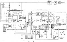
What you get from the 3 phase coils ought to be a 50kHz carrier wave, whose envelope is amplitude modulated with a sinusoid of around 6Hz. AM demodulation - i.e., boring old envelope detection is done with a Ge diode pair on the SP10 & gives a pair of 6Hz sinusoids of opposite phase.
Maybe non-linearity in the diode detector is creating the distortion?
Is a 'nice' waveform really necessary? Mechanical inertia, and the negative feedback property of the PLL get flutter figures below anything I'd ever be able to measue - and certainly no be able to hear.
The alternative - as you say - is ignoring these signals altogether, and using a PIC to create 3 sines of variable frequency - somewhere around 6 Hz. I was avoiding thinking about it because I hate writing assembler! But in principle, its not dificult - just a sine look-up table and appropriate delay loops in the right places.
Hows your MPASM?
It would still require an analogue control loop I think - because unless you drive the motor at high current all the time, there will be a phase lag that is dependent on load torque.
Originally posted by Steerpike
I was avoiding thinking about it because I hate writing assembler! But in principle, its not dificult - just a sine look-up table and appropriate delay loops in the right places.
Hows your MPASM?
You don't have to write in assembler. There are C compilers available that makes it much easier. I have written PIC programs back when I was studying both in assembler and C, but I never used thereafter (I'm rather regretting that now!). But I have friends and colleagues who can help me get up to speed, should I need to go that route.
I think you may be right. The waveform is not nice, but that could be the electronics, and we aim to replace them!
I'm out for perfection and any increase in sinusoidal drive performance will help. I have an current Microchip Technology PICSTART Programmer, but only to blow chips from code people send to me. I'm not a logic or firmware designer, I'm analogue only and good at that!
On the unit as supplied, if you try to slow it down using your hand, you can see the strobe marking move slightly, still in hard lock, but displaying a phase shift. Also the current goes up to nearly 1A from the 32V supply which normally is about 100mA.
Regards
Dave
I had a glance at a Mk3 service manual recently, and was surprised to see what looked like trapezoidal waveforms represented there...😕
- Home
- Source & Line
- Analogue Source
- New Technics SP10 motor controller specification