hi gychang,
I from italy and I've a problem whit the 6 channel pcb, tripath, in front channel there is a little AC tension, have you ?
sorry for my english
I from italy and I've a problem whit the 6 channel pcb, tripath, in front channel there is a little AC tension, have you ?
sorry for my english
ahio said:hi gychang,
I from italy and I've a problem whit the 6 channel pcb, tripath, in front channel there is a little AC tension, have you ?
sorry for my english
I have the MKIII SET board, which sounded excellent on brief listening, I am considering trying MKII board.
gychang
How to connect the powerswich
Hello,
I bought the TA2020 2x25W board, and it sounds great 😀,
My question is, how do I connect the powerswith that came along? It has 3 pins, 2 silver and 1 gold pin. 😕
Thanks in advance
Hello,
I bought the TA2020 2x25W board, and it sounds great 😀,
My question is, how do I connect the powerswith that came along? It has 3 pins, 2 silver and 1 gold pin. 😕
Thanks in advance
Re: How to connect the powerswich
I have the same board and same questions. also LED connection.
gychang
Ganjou said:Hello,
I bought the TA2020 2x25W board, and it sounds great 😀,
My question is, how do I connect the powerswith that came along? It has 3 pins, 2 silver and 1 gold pin. 😕
Thanks in advance
I have the same board and same questions. also LED connection.
gychang
ArjenShenzhen said> i have just finished a nice PDF explaining how to mod this board and get the best out of it, any one that wants this file, please drop me a mail and ill send it to you .
Hello there. New here, but very interested in the modded version of this board. I would want to power 5.1 speakers using analogue connects from my PC via this amplifier.
Is this a product that someone with minimal experience in this area could use for this? (got experience building computers however).
Anyway, just dropped you an email asking for the PDF as well as well as the easiest way to set this up to power 5.1 speakers from a PC using analogue connections and what other parts would be needed.
Thanks.
1. What's the best way to buy this product? PM/email you direct or go to your ebay shop? (Note that I can't PM you or email you from this forum as I am a new member, so you need to drop me your email)
2. Would like to have 6 full range channels. How much for the upgrade?
3. Does this accept the 3 traditional 5.1 analogue inputs (i.e. front left & right. Centre + subwoofer. Rear left & right.). I am simply connecting my PC sound card here via normal analogue cables.
4. Does this have traditional 6 channel analogue outputs?. (i.e. front left, right, centre. Rear left, right. Subwoofer.) I am simply connecting a traditional 5.1 speaker system here.
5. Can I just plug in European voltage or so I need an adaptor? Or am I better off with my own PSU and using 12volts - if so, is it easy to put in the PSU?
5. Any cases you know of or recommend that I can put this in?
Thanks.
TA2020 wiring
I have one of these 'new' TA2020 from Arjen.
I'm just getting round to wiring it up now and struggling to get my hear round the wiring from input - selector - pot - pcb.
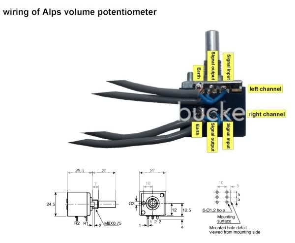
I've worked out the alps pot pins, but my question is this:
The pcb only has one earth, so where does this connect to on the pot?
Does it connect to both earth pins?
Also the input selector has three output pins - presumably you connect both L and R input earths to one input pin on the selector? So the same question applies, do you connect this common input earth to one or both Pot earth pins?
Also - on the three pin pcb input, one is marked earth - which of the other two is Left and which Right?
I'm housing this in an aluminium case, with power transformer inboard. This will be high gloss powder blue enamel painted. On the front, three cream chicken-head knobs will provide: rotary on/off via a lorlin rotary switch; four-way input selection; and volume control. Very retro!
I'm very excited, but just got to get my head around this input wiring.....
I'm attaching this useful diagram of the Alps pot to help others
thanks anyone!
I have one of these 'new' TA2020 from Arjen.
I'm just getting round to wiring it up now and struggling to get my hear round the wiring from input - selector - pot - pcb.
I've worked out the alps pot pins, but my question is this:
The pcb only has one earth, so where does this connect to on the pot?
Does it connect to both earth pins?
Also the input selector has three output pins - presumably you connect both L and R input earths to one input pin on the selector? So the same question applies, do you connect this common input earth to one or both Pot earth pins?
Also - on the three pin pcb input, one is marked earth - which of the other two is Left and which Right?
I'm housing this in an aluminium case, with power transformer inboard. This will be high gloss powder blue enamel painted. On the front, three cream chicken-head knobs will provide: rotary on/off via a lorlin rotary switch; four-way input selection; and volume control. Very retro!
I'm very excited, but just got to get my head around this input wiring.....
I'm attaching this useful diagram of the Alps pot to help others
thanks anyone!
echn111 said:5. Any cases you know of or recommend that I can put this in?
Thanks.
I notice you are in the UK - I bought a case like this from RS electronics which will house the plain stereo TA202 board plus Arjen's power adapter. There's a range of sizes available. I've been drilling the necessary holes with a hand drill and wood drill bits - it's alloy and so drills easily. I'm enamel painting it and then I'll put little rubber feet on
Banzai (where the image is linked to) do a good range of knobs too
An externally hosted image should be here but it was not working when we last tested it.
I have only guesses for how to hookup the amp so a little documentation could be very useful.
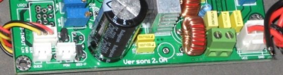
For example, between a choke and the 12v power VCC/GNDare a set of green screw terminals. I have no idea what they are for. What do I hook those up to?
The two white "over" and "pow" terminals are vague. I imagine that these are for the LEDs. I'm not sure about the orientation, +/-.
Thanks.
For example, between a choke and the 12v power VCC/GNDare a set of green screw terminals. I have no idea what they are for. What do I hook those up to?
The two white "over" and "pow" terminals are vague. I imagine that these are for the LEDs. I'm not sure about the orientation, +/-.
Thanks.
Attachments
Yes, I believe your version is the revision after mine.
On mine, the power LED and Overload protection LED are mounted onboard.
Yours has terminals instead, allowing you to mount the LEDs on the facia - I thought it shipped with the necessary leads and LEDs, but perhaps not.
As LEDs only work in one direction, it shouldn't be hard to ascertain the polarity of the power one. One would then assume the overload would be the same.
As for the green block - I've no idea - there doesn't seem to be anything like that on mine.
Out of interest, with reference to my first post on this topic, of the three cables yellow, black and red / LIN, GND and RTN - which of LIN and RTN is Left and which Right? These link to your potentiometer don't they?
And do they, as I assume, stand for Line and Return? If so why?
Sorry - I'm a novice, so these may be fundamentals I should perhaps already have a grasp of prior to embarking on building my first T-Amp.
LIN is Left In
RTN is probably RIN, Right In
I've only given the board a cursory glance.
From what I can gather, if a multimeter shows connectivity (zero ohms) to the red input caps (edge side), then a pot should hookup directly to the red/black/yellow. I'll check tonight and let you know.
I use resistor ladders. They sound about 1,000 times better than the tiny carbon pots. Search Ebay for "volume ladder". A mildly cheaper alternative is Alps or Noble.
Regarding the LEDs. I don't want to experiment to find out if I wired the Overload correctly.
The green terminal block is a complete mystery. If they aren't hooked up correctly will I end up destroying the amp?
The red/yellow/black input wires can go directly to the volume pot. There's no need to mess with the pads on the pcb. This is nice but I might anyway.
The green terminal block is for AC power in. I am going to use an SMPS so there's no reason for me to use it.
I'll figure out the LED orientation when I get the power supplies.
The Audiophiler caps on the board are not Mundorf Audiophiler caps. I will give them a listen, perhaps 100 hours or burn in.
I have an assortment of MKP and PIO caps to try. I have been told that Vishay MKY 1822 sound very good in the T amps. I have a set of 4.7uf I will try.
I'm going to give it a run in once my power supplies arrive from wherever on the other side of the planet. Until then, Ciao.
Mush said:The red/yellow/black input wires can go directly to the volume pot.
The green terminal block is for AC power in. I am going to use an SMPS so there's no reason for me to use it.
The Audiophiler caps on the board are not Mundorf Audiophiler caps. I will give them a listen, perhaps 100 hours or burn in.
I have an assortment of MKP and PIO caps to try.
I have the same board, is the green terminal block for AC power?, am confused. will the amp work if AC power is connected?
I have the same version 2 board and will be very interested in different input caps, please report back on the sound.
gychang
I don't think using an AC supply is a good idea. Over voltage is possible. My wall socket puts out 125vac. A power transformer with 115vac primary will run over published specification.
An switching supply is regulated. I bought a 12volt @ 10A supply through Ebay. It's not here yet.
I usually don't have much time so my experiments are slow.
If you want to see someone else's opinion on the Audiophiler caps, see this thread.
http://www.diyaudio.com/forums/showthread.php?threadid=139014
Here's a review of the Vishay MKT 1822 (which cost almost nothing, I wrote MKY by mistake in the earlier post, sorry)
http://www.diyaudio.com/forums/showthread.php?postid=1265877#post1265877
I notice you are in the UK - I bought a case like this from RS electronics which will house the plain stereo TA202 board plus Arjen's power adapter. There's a range of sizes available. I've been drilling the necessary holes with a hand drill and wood drill bits - it's alloy and so drills easily. I'm enamel painting it and then I'll put little rubber feet on
Banzai (where the image is linked to) do a good range of knobs too
Thanks - will look into these. I'm not so good with modding, and was hoping for something that already included a volume knob, an on/off switch and room at the back for the connectors.
I have the same board, is the green terminal block for AC power?, am confused. will the amp work if AC power is connected?
I have the same version 2 board and will be very interested in different input caps, please report back on the sound.
gychang
Not sure if you have the same board I bought, but I connected AC power to CN401, which is the top most power connector and it worked (and put the on/off switch against SW402). Specifically, I chopped up a normal AC cable and connected the two non-ground wires to CN401 and just left the ground alone.
I considered asking for an external power supply as all this board really needs is 12v @ 10A, but it handles the 230v AC power I'm feeding it, which is within the specification in Arjen's documentation, and converts it. So far so good.
I've just got the MK2 board, and it sounds great....My only question is about the Red 'Overload' LED. It starts Glowing to the Music when I get over 11:00. Am I asking too much from my 13v 1.8A PS. or is this just what it does normally?
Hi Arjen!
I've got my amplifier today(Igor from Slovenia). I quickly soldered all parts and now it's playing. 🙂
On first impression it sounds little worse than my previous modded T-amp(your first revision). Bottom end is little thick in comparison with old modded. But I already ordered better input caps(Vishay and M-cap) and we'll see then how it will play. What is maximum DC input voltage?
If you have any tips for modding, I would appreciate if you send them on pm.
Regards,
Igor
Here is my finished amp:
An externally hosted image should be here but it was not working when we last tested it.
An externally hosted image should be here but it was not working when we last tested it.
An externally hosted image should be here but it was not working when we last tested it.
An externally hosted image should be here but it was not working when we last tested it.
An externally hosted image should be here but it was not working when we last tested it.
- Status
- Not open for further replies.
- Home
- Vendor's Bazaar
- New ta2020 pcb'S