. I also converted it to PDF format - it's distorted a bit, but still readable. I put both in my Dropbox:
PDF File
Ed
I fixed the PDF:
https://dl.dropboxusercontent.com/u/5641160/Sure ADAU1701 Manual.pdf
Hi,
I am a bit confused here, I read the Sure manual but it's still not clear to me...
I have an original USBi from ADI and the latest SigmaStudio, did anyone manage to make it work with the Sure board directly with a 10 to 6 pin adaptor?
Thanks
M
I am a bit confused here, I read the Sure manual but it's still not clear to me...
I have an original USBi from ADI and the latest SigmaStudio, did anyone manage to make it work with the Sure board directly with a 10 to 6 pin adaptor?
Thanks
M
Last edited:
It should work, see post #66. Are you executing the ADI_USBi.spt script? That needs to be done before SigmaStudio will work.
Thanks a bunch for the tip.
I haven't bought it yet, I am just planning a RPI for FIR on either:
Runeaudio DRC, Volumio DRC, probably not Kodi as media player + Digital Room Correction to feed a two way active pair of monitors.
The Sure DSP would cover the X-over job plus some light EQ to get the speaker right in the first place. I am very attracted to the possibility of using SigmaStudio directly rather than the MiniDSP type of SW that is locked into a predefined structure.
M
The chip may be able to output 4 channels. It would be interesting if someone figures out if this is possible.
It's the expansion board (the one with RCA connectors) that limits you to the 2.1 format. All four channels (DAC0 - DAC3) are available on the 1701 board's 10 pin connector along with the two analog channel inputs, power, signal ground, etc.
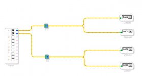
Here are a few tests I ran on the Sure 1701 board. I was interested in the board's frequency response and harmonic distortion, especially since it doesn't appear to have reconstruction filters. I performed the tests in two different configurations: one using the Sure extension board (the board with the RCA connectors) for inputs/outputs and a second using the 1701 board's 10-pin extension connector lines directly. To perform the tests I created and downloaded a SigmaStudio program that simply maps input 0 directly to DACs 0 and 1 and input 1 directly to DACs 2 and 3.
I first ran a static test at 1 KHz to determine the loss between inputs and outputs. The 1701 board is configured for a maximum of 2 Vrms input and the maximum DAC outputs are 0.9 V. That calculates to an expected loss of 6.9 dBV. Using the 10-pin connector I measured a loss of 7.5 dB, 0.6 dB more than expected. I then repeated the same test using the RCA extension board for inputs/outputs and got my first surprise: an average loss of only 1.5 dB. The extension board must be providing about 6 dB of gain on the input before sending it to the 1701 board. The question I have to ask myself is how? The only ICs I see are the two SGM4917 headphone amps Neil Davis mentioned in post #32. Since I'm not really interested in the extension board I don't plan to pursue the answer.
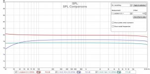
I then ran frequency response and harmonic distortion tests using both configurations. In an attempt to keep the 1701 DAC output at the same level for both configurations I ran the extension board tests at 0.5 V (approximately half full scale) and the 10-pin connector tests 6 dB higher (1.0 V), also approximately half full scale. I also ran a loopback test at 0.5 V to measure my system's baseline response and harmonic distortion. I attached the comparison measurements for SPL, phase and distortion. My interpretation of the measurements:
SPL: The upper red trace (loop back) and the lower green trace (DAC0 using 10-pin connector inputs/outputs) are pretty much straight lines. The middle blue trace (DAC0 using extension board inputs/outputs) shows the extension board adds a high pass filter that rolls off very low bass. And it looks like I should have raised the 10-pin input level one more dB to match the extension board output level.
Phase: The red loopback trace is at or near 0 degrees as expected. The lower green trace (DAC0 using 10-pin connector inputs/outputs) is at or near -180 degrees. That's because the 1701 DACs are inverting DACs as explained in the 1701 datasheet. The upper blue trace (DAC0 using extension board inputs/outputs) shows the phase shift due to the high pass filter and then approaches 0 so the extension board must also invert the signal. Perhaps an inverting active high pass filter with gain?
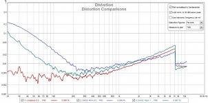
Distortion: The lower red loopback trace starts off at a respectful 0.005%, but starts increasing at around 500-700 Hz to 0.03% at 7 KHz. I don't know exactly why that's happening unless it's a flaw in my audio interface (a USB/Firewire Behringer FCA610). Something to investigate later. The upper blue trace (DAC0 using extension board inputs/outputs) has higher distortion in the 20 to 300 Hz region than DAC0 using the 10-pin connector (middle green trace), perhaps from the high pass filter. But notice that from about 300 Hz and above the distortion using either set of inputs/outputs is near the distortion floor of my system. I really didn't expect this from the 1701 board, especially if it doesn't have reconstruction filters. One thought is whether my Behringer has low pass filters on its inputs in the 50 KHz range that act as reconstruction filters. Just a guess.
Next up: I have two class D amps, a Sure TDA3116 board (AA-AB32178) and a Sanwu mono TPA3118 board. I plan on running the same types of tests with the each board alone and then repeat with the 1701 board in the loop, keeping the amp's output the same (e.g. 1W). I'll post my results.
I first ran a static test at 1 KHz to determine the loss between inputs and outputs. The 1701 board is configured for a maximum of 2 Vrms input and the maximum DAC outputs are 0.9 V. That calculates to an expected loss of 6.9 dBV. Using the 10-pin connector I measured a loss of 7.5 dB, 0.6 dB more than expected. I then repeated the same test using the RCA extension board for inputs/outputs and got my first surprise: an average loss of only 1.5 dB. The extension board must be providing about 6 dB of gain on the input before sending it to the 1701 board. The question I have to ask myself is how? The only ICs I see are the two SGM4917 headphone amps Neil Davis mentioned in post #32. Since I'm not really interested in the extension board I don't plan to pursue the answer.
I then ran frequency response and harmonic distortion tests using both configurations. In an attempt to keep the 1701 DAC output at the same level for both configurations I ran the extension board tests at 0.5 V (approximately half full scale) and the 10-pin connector tests 6 dB higher (1.0 V), also approximately half full scale. I also ran a loopback test at 0.5 V to measure my system's baseline response and harmonic distortion. I attached the comparison measurements for SPL, phase and distortion. My interpretation of the measurements:
SPL: The upper red trace (loop back) and the lower green trace (DAC0 using 10-pin connector inputs/outputs) are pretty much straight lines. The middle blue trace (DAC0 using extension board inputs/outputs) shows the extension board adds a high pass filter that rolls off very low bass. And it looks like I should have raised the 10-pin input level one more dB to match the extension board output level.
Phase: The red loopback trace is at or near 0 degrees as expected. The lower green trace (DAC0 using 10-pin connector inputs/outputs) is at or near -180 degrees. That's because the 1701 DACs are inverting DACs as explained in the 1701 datasheet. The upper blue trace (DAC0 using extension board inputs/outputs) shows the phase shift due to the high pass filter and then approaches 0 so the extension board must also invert the signal. Perhaps an inverting active high pass filter with gain?
Distortion: The lower red loopback trace starts off at a respectful 0.005%, but starts increasing at around 500-700 Hz to 0.03% at 7 KHz. I don't know exactly why that's happening unless it's a flaw in my audio interface (a USB/Firewire Behringer FCA610). Something to investigate later. The upper blue trace (DAC0 using extension board inputs/outputs) has higher distortion in the 20 to 300 Hz region than DAC0 using the 10-pin connector (middle green trace), perhaps from the high pass filter. But notice that from about 300 Hz and above the distortion using either set of inputs/outputs is near the distortion floor of my system. I really didn't expect this from the 1701 board, especially if it doesn't have reconstruction filters. One thought is whether my Behringer has low pass filters on its inputs in the 50 KHz range that act as reconstruction filters. Just a guess.
Next up: I have two class D amps, a Sure TDA3116 board (AA-AB32178) and a Sanwu mono TPA3118 board. I plan on running the same types of tests with the each board alone and then repeat with the 1701 board in the loop, keeping the amp's output the same (e.g. 1W). I'll post my results.
Attachments

Here are a few tests I ran on the Sure 1701 board.
Thanks for doing this. I was curious how well the I/O board performed. It uses a pair of SGM4917 headphone amps to buffer the outputs, which is an unusual choice.
The SGM4917 has an on-board charge pump to provide a negative voltage, which has two benefits. First, it allows the output to swing above and below ground so that you don't need an output capacitor. And second, it increases the total voltage swing to get more output than what is usually possible from a 3.3V device. That allows the I/O board to compensate for that 6dB loss in the ADAU1701 from using the 2V input. So it looks like the DSP board with the I/O board provides pro-gear compatible voltage levels on both input and output (nominal 2V input and 2V output).
I'm thinking about posting a 2.1 amplifier project that uses this board. It would use an Arduino board to control the Sure DSP, including the load, and would have a Nextion touch-screen display that would allow the user to control the crossover frequencies and slope. It would also incorporate some of the Analog Devices bass enhancement algorithms. I've already got a custom 3-way ADAU1701 board working and this project would be a spin-off of that using commercial boards.

Noise problem
Hi Guys,
I’m Kraven (Daniel) from Hungary.
First of all, I have to apologise for my poor english. I hope you will be able to understand what I’m writing…
I’m not absolute beginner in the electronical diy, but newbie in the digital DSP’s world.
About my project: I would like to build a 5.2 home theater system. All of the speakers are DIY 2,5 way (4 speaker), active crossover (ADAU DSP) with D class TPA3116D2 amps.
I’m doing the first „test runs” with my center speaker, but unortunatenny I have a big trouble. The noise. I have a noise floor, what is absolutely not accepteble for me.
I have 4 pcs of Sure ADAU1701 Kernel board and extension board. I use Sure in-circuit programmer and of course the Sigma Studio. Each pc of kerner board have different program. (original Sure program, 2 way crossover, 3way crossover and a pass throu)
3 different kind of power source for the amps and for the kernel boards (swiched mode, classic with toroid transformator, and accumulator) 9 different amp board (TPA3116, STK, STU, TDA, types). All of the configures shows the same: The single amp board’s have different size of HISS (moderate, acceptable size). And when I connect the kernel board and turn it on, this HISS increase to loud and the noise is absolutely independent from the volume. Crazy… Maybe the active ADAU1701 generates this size of noise? When I turn it off, the noise decrease to moderate size. All the four kernel boards show these unacceptable action.
I tried all the possible connection modes (extension board RCA, extension board 4PIN, kernel board 20 pin connector, etc) The best is the 20 pin connector of the kernel board, and worst is the extension board’s RCA. But the best config has VERY big noise too. I can’t do frecvency measurement, because my mic can’t calibrate itself because of the loud HISS.
On the other way the DSP does it’s job. The programs run without problem, I can do the set ups in „real time”with the in-circuit progammer, so I feel this is a very useful gadget. I would like to use it…
I do something wrong. But what?
Thanks a lot
Kraven
Daniel - I can think of a few areas that might be causing your noise problem:
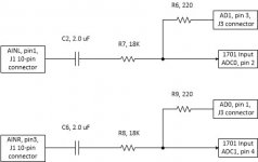
1. Don't use the AD0 and AD1 inputs on the J3 20-pin connector. I recently discovered these inputs bypass the input capacitor and 18 KOhm resistor which are needed. When using the 1701 board alone use the AINL and AINR inputs on the J1 10-pin connector or use the extension board with RCA inputs. See my attached input sketch.
2. Amp gain setting: TPA3116 amps can be set up for 20, 26, 32 or 32 dB of gain. Amps set to 26 dB of gain work best with the 1701's DACs' maximum output level. A gain of 20 dB will work and is the quietest, but you'll be limited to 20 W (using a 4 ohm load) when the DACs are at their output maximum of 0.9 V. Several people have noticed hiss with amp boards using 32 or 32 dB of gain.
3. Grounding: The J1 10-pin connector has two types of ground connections: pin 9 is "GND" and pin 2 is "SGND". I've always connected the negative side of the input to "SGND" and not used "GND" at all.
4. Input level: if you're using the 1701 board alone without the RCA extension board you should ideally use an input device that can produce up to 2 Vrms to the 1701 board. If you're using the extension board 1 Vrms is the maximum input.
5. SigmaStudio program: For testing I'd recommend that you replace the SigmaStudio program that comes with the board with a simple program that just routes the input 0 to DACs 0 &1 and input 1 to DACs 2 & 3. That assumes you have a 1701 programmer.
To assist everyone with your problem you could post your setup details, including source, amp and a diagram of all the connections.
Attachments
Last edited:
Dear ernperkins,
Thank you for your comment.
Your 1, 3, 4, 5 points: I've tried them. Unfortunately nothing results. :-(
At the moment the conections are according to your tips.
The noise is there without any input too. If I make the connektions withot power on the kernel there are only a moderate size of hiss, so the noise doesn't come from EMI. If I power on the Kernel board the noise appear. With signal input, without signal input and with shortstopped input too.
About point 2: Maybe you're right. My first idea was the gain problem too, but I thought that the kernels's board gain is too high. I've tried to decrease the ADAU's gain with the sigma software. Without any success... Can I decrease the kernel's gain in the board? Sure, but unfortunately my eyes aren't sharp enough to make soldering on a surface mounted PCB. Is there any other possibility?
I will try the config with a lower level gain amp. (I must realize how can I set the gain level in the finished amp board)
At home I will try to make a pic about my sigma software and the connected device too.
Thank you again!
...
I'm thinking about posting a 2.1 amplifier project that uses this board. It would use an Arduino board to control the Sure DSP, including the load, and would have a Nextion touch-screen display that would allow the user to control the crossover frequencies and slope. It would also incorporate some of the Analog Devices bass enhancement algorithms. I've already got a custom 3-way ADAU1701 board working and this project would be a spin-off of that using commercial boards.
Please do - thank you! 😀
SGM4917 take analog output from ADAU1701 dacs. If one is going to use digital amp at the output, then I2S outputs from ADAU1701 directly to amp would be a better choice.
lf distortion
the LF distortion could also be a jitter introduced S/N problem. the ADAU needs an xtal controlled dac freq, not a pll reconstructed digital input stream
Here are a few tests I ran on the Sure 1701 board. I was interested in the board's frequency response and harmonic distortion, especially since it doesn't appear to have reconstruction filters. I performed the tests in two different configurations: one using the Sure extension board (the board with the RCA connectors) for inputs/outputs and a second using the 1701 board's 10-pin extension connector lines directly. To perform the tests I created and downloaded a SigmaStudio program that simply maps input 0 directly to DACs 0 and 1 and input 1 directly to DACs 2 and 3.
I first ran a static test at 1 KHz to determine the loss between inputs and outputs. The 1701 board is configured for a maximum of 2 Vrms input and the maximum DAC outputs are 0.9 V. That calculates to an expected loss of 6.9 dBV. Using the 10-pin connector I measured a loss of 7.5 dB, 0.6 dB more than expected. I then repeated the same test using the RCA extension board for inputs/outputs and got my first surprise: an average loss of only 1.5 dB. The extension board must be providing about 6 dB of gain on the input before sending it to the 1701 board. The question I have to ask myself is how? The only ICs I see are the two SGM4917 headphone amps Neil Davis mentioned in post #32. Since I'm not really interested in the extension board I don't plan to pursue the answer.
I then ran frequency response and harmonic distortion tests using both configurations. In an attempt to keep the 1701 DAC output at the same level for both configurations I ran the extension board tests at 0.5 V (approximately half full scale) and the 10-pin connector tests 6 dB higher (1.0 V), also approximately half full scale. I also ran a loopback test at 0.5 V to measure my system's baseline response and harmonic distortion. I attached the comparison measurements for SPL, phase and distortion. My interpretation of the measurements:
SPL: The upper red trace (loop back) and the lower green trace (DAC0 using 10-pin connector inputs/outputs) are pretty much straight lines. The middle blue trace (DAC0 using extension board inputs/outputs) shows the extension board adds a high pass filter that rolls off very low bass. And it looks like I should have raised the 10-pin input level one more dB to match the extension board output level.
Phase: The red loopback trace is at or near 0 degrees as expected. The lower green trace (DAC0 using 10-pin connector inputs/outputs) is at or near -180 degrees. That's because the 1701 DACs are inverting DACs as explained in the 1701 datasheet. The upper blue trace (DAC0 using extension board inputs/outputs) shows the phase shift due to the high pass filter and then approaches 0 so the extension board must also invert the signal. Perhaps an inverting active high pass filter with gain?
Distortion: The lower red loopback trace starts off at a respectful 0.005%, but starts increasing at around 500-700 Hz to 0.03% at 7 KHz. I don't know exactly why that's happening unless it's a flaw in my audio interface (a USB/Firewire Behringer FCA610). Something to investigate later. The upper blue trace (DAC0 using extension board inputs/outputs) has higher distortion in the 20 to 300 Hz region than DAC0 using the 10-pin connector (middle green trace), perhaps from the high pass filter. But notice that from about 300 Hz and above the distortion using either set of inputs/outputs is near the distortion floor of my system. I really didn't expect this from the 1701 board, especially if it doesn't have reconstruction filters. One thought is whether my Behringer has low pass filters on its inputs in the 50 KHz range that act as reconstruction filters. Just a guess.
Next up: I have two class D amps, a Sure TDA3116 board (AA-AB32178) and a Sanwu mono TPA3118 board. I plan on running the same types of tests with the each board alone and then repeat with the 1701 board in the loop, keeping the amp's output the same (e.g. 1W). I'll post my results.
the LF distortion could also be a jitter introduced S/N problem. the ADAU needs an xtal controlled dac freq, not a pll reconstructed digital input stream
- Home
- Source & Line
- Digital Line Level
- New? Sure Electronics ADAU1701 Module